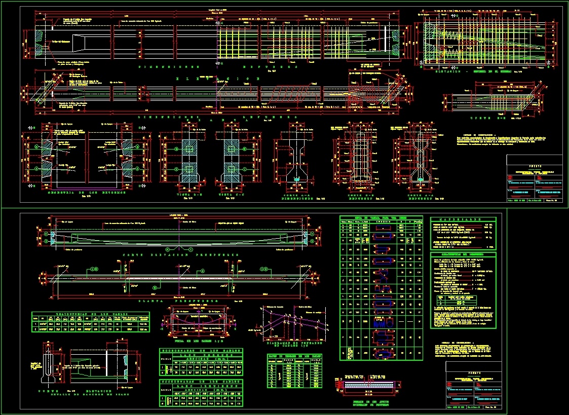
Postensioned Beam DWG Block for AutoCAD
Postensed beam for 20.00 m wide and 1.15 high with skew
Drawing labels, details, and other text information extracted from the CAD file (Translated from Spanish):
vars.l, the cable and injected the duct., which will be made after tensioning, casting for mobile anchor seal, geometry of the extreme s, cortea – a, dimensions, vistab – b, vistac – c, corted – d, reinforcement, this surface should be left rough, elevation – reinforcement at the end, construction standards:, for materials construction procedures and general project specifications will be applicable, standards contained in the new regulations for the transport infrastructure of the sct as well as the, particular specifications that are indicated in the catalog of concepts and quantities of work., dimensions.- in centimeters except those indicated in another unit., cortee – e, dimensions, elevation, reinforcement, symmetric, see detail of the reinforcement, from the extremes, for materials construction procedures and specifications, general project will be applicable the standards contained in the new regulations for the transport infrastructure of the sct, as well as the particular specifications that are indicated in the cata- logo of concepts and quantities of work., cutting and raising, ground pressure, low-pressure pre-stress steel, strands, kg., pcs., prestress characteristics, number, diameter of the strands and steel area, mod Elastic assumption in, coefficient of friction with, assumed slip in, total stress in operation, tensioning form: will be tensioned by, cable, no., length between outer panels, of the anchoring plates, the application of the prestress will be made when the concrete of the trabe has one, after applied the prestress will be contraveteará, stiffens adequately me-, in order to reduce to the maximum the risk of failure by lateral buckling during the, it is indispensable that the injection of slurry of the ducts, is made Immediately after the tensioning and anchorage of the cables, the geometry of the ends of the bars allows the use of anchors, trajectories of the cables, strands, no. of, garea loading, expected, deformation, cable, cable coordinates s, right side, ordinates, left side, materials, tension diagrams, parabolic trajectory, straight, origin of coordinates, center of clearing, t ”, effort, unit, tension data of the cables, support axis, prestressing steel, the pipeline, by linear meter, the pipeline by bending, the cables when anchoring, by fastening to the center of the clearing, one end and anchoring in the opposite, maneuvering the same., neoprene shore hardness, detail of the supports, neoprene integrals, detailofdeposits, elevation, type rattle, each cable, length of, cut, list of rod for a trabe, vars., diam., num., l. total, sketch, cable type casca-, plant, superstructure trabes pos tense, p u n t e, ——, review:, approved:, the head of the general service unit. tec., the general director of the center s.c.t., date:, vo. bo., ———, the deputy director of works, the gral resident. of carr. feeders, ———–, section:, state:, road:, km. :, dimensions and reinforcement
Raw text data extracted from CAD file:
| Language | Spanish |
| Drawing Type | Block |
| Category | Roads, Bridges and Dams |
| Additional Screenshots |
 |
| File Type | dwg |
| Materials | Concrete, Steel, Other |
| Measurement Units | Metric |
| Footprint Area | |
| Building Features | |
| Tags | autocad, beam, block, bridge, DWG, high, wide |
Related Products


Same Contributor

Featured Products


