Cistern DWG Detail for AutoCAD

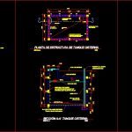
DETAIL CISTERN AND DESCRIPTION ELEMENTS OF ELEVATED TANK
Drawing labels, details, and other text information extracted from the CAD file (Translated from Spanish):
Comes from the street, Stopcock, accountant, Gate key, check, bomb, hydropneumatic tank, Towards house circuit, Vent to keep water oxygenated, Suction pipe pvc, check, Entrance duct, Float valve, Cistern operating detail, scale, Goes to the house service, Pipe coming from the meter without, Horizontal check, Tee of counter diameter, Globe valve for input control, Tube equal to the diameter, Tee of the rise pipe diameter, Pipe diameter copla, Nipple run with two packings, Check direction of the water outlet, Elbow of the pipe diameter, float, Pvc vent diameter, tee, Water outlet of the tank, Given service, High tank detail, unscaled, Balloon stopcock, pending, Projection duct input, stairs, Indoor swimming pool sika coating, Armed not. Esl. do not. row, do not. Esl. do not. row, Tank tank structure plant, scale, Ground level, Upper slab, Marine corrugated iron ladder with lined poliducto, buoy, focus, water level, pending, Foot valve, Pvc tube, do not. In both directions welded mesh, Pipe goes hydropneumatic equipment, scale, Tank tank section, scale, Ventilation detail, open, do not., do not. In corners, do not., water level, Hg tube, Copper mesh fine mesh of hg, Upper slab reinforcement tank tank plant, scale, hydropneumatic tank, Level guard, bomb, Pipe, Foot valve pichacha, Electrodes guard, pressure gauge, check, Pipe, Installation detail of hydropneumatic tank pump, unscaled, Soil level, Reservoir water tanks are used in places where water pressure is irregular in which this solves the problem of water scarcity during the low pressure period of high consumption. Tank that works by gravity this tank is suggested that this in the highest part of the house must be installed at least m. Of height of the equipment that goes in which it is supplied directly from the municipal had to avoid being overloaded is placed a float valve end of the filling had. Pressure tank driven by a pump this type of tank is connected connected to the pump to the distribution system can be located anywhere its use is more frequent in the rural arias by the low pressure to raise water pump operation For the pressure tanks when the pump is filled the bottom of the trap being trapped a quantity of air in the upper part when the tank is filled up the water level compressing the trapped air. When the air pressure rises to a value of kg. Per square centimeter a pressure switch disconnects the motor. The pressure switch is set so that the pump will start again when the water reaches the pressure drops by a value of per square centimeter. Functioning of the system the distribution of water in the house is located in the plan of installation in which the floor of the house is realized showing the passage of the main pipe its des of the entrance of the house the different environments like lava tackle of the The trough the hot water pipe that should go to the left side of the appliance.
Raw text data extracted from CAD file:
| Language | Spanish |
| Drawing Type | Detail |
| Category | Mechanical, Electrical & Plumbing (MEP) |
| Additional Screenshots |
 |
| File Type | dwg |
| Materials | |
| Measurement Units | |
| Footprint Area | |
| Building Features | Pool, Car Parking Lot |
| Tags | autocad, cistern, description, DETAIL, DWG, einrichtungen, elements, elevated, elevated tank, facilities, gas, gesundheit, l'approvisionnement en eau, la sant, le gaz, machine room, maquinas, maschinenrauminstallations, provision, tank, wasser bestimmung, water |

