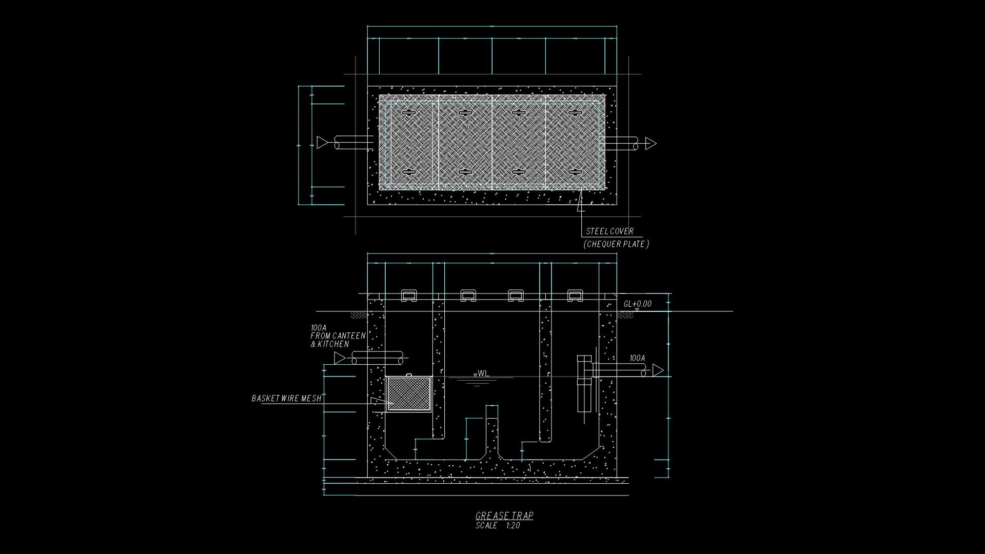
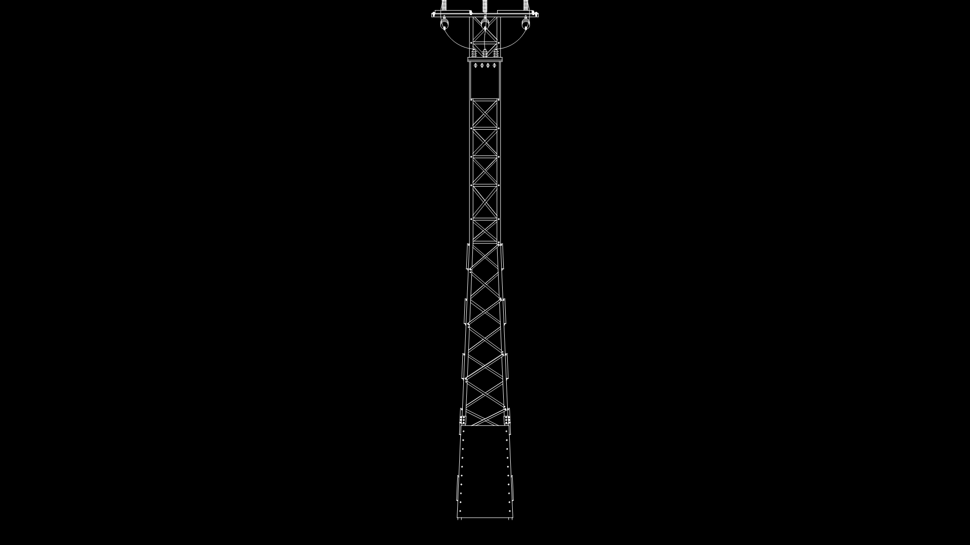
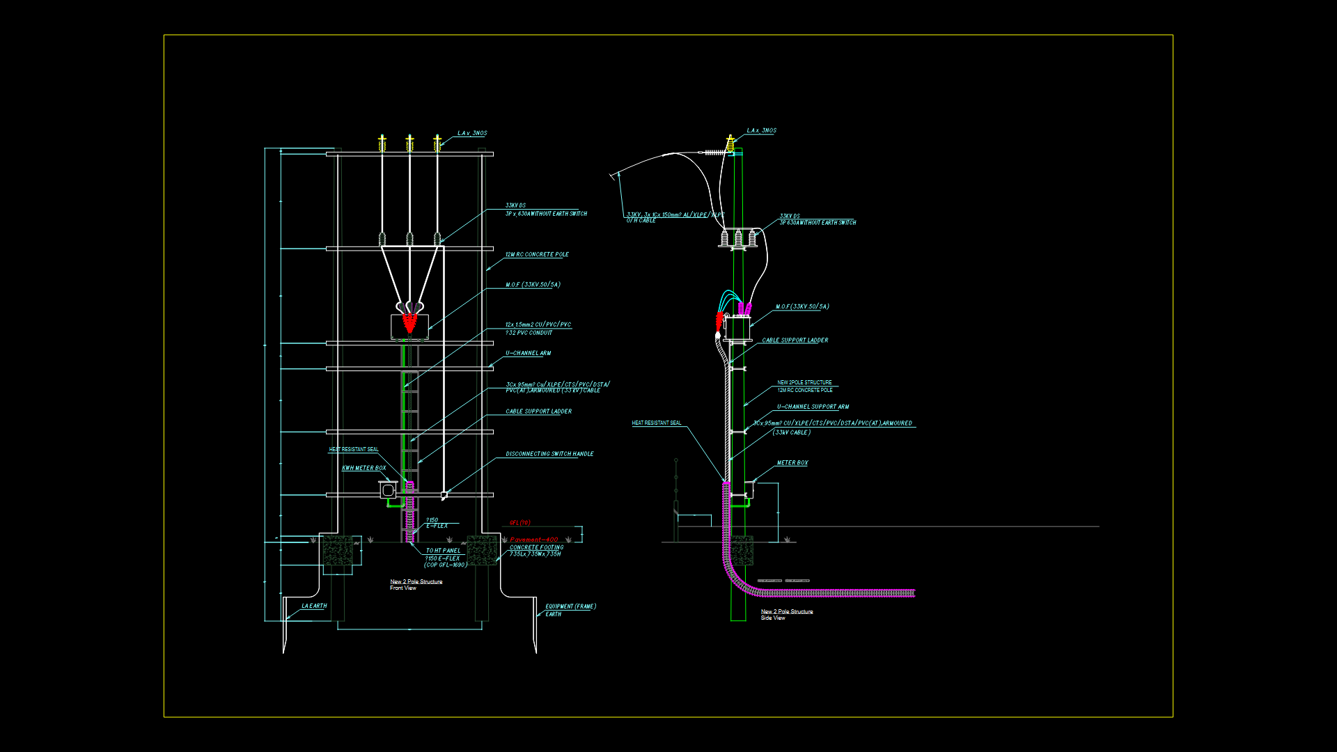
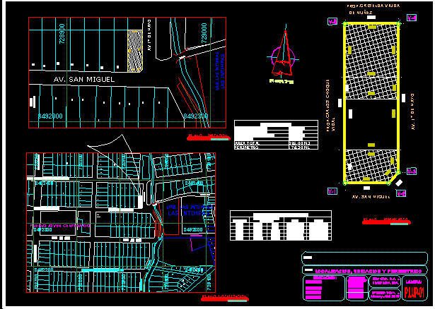
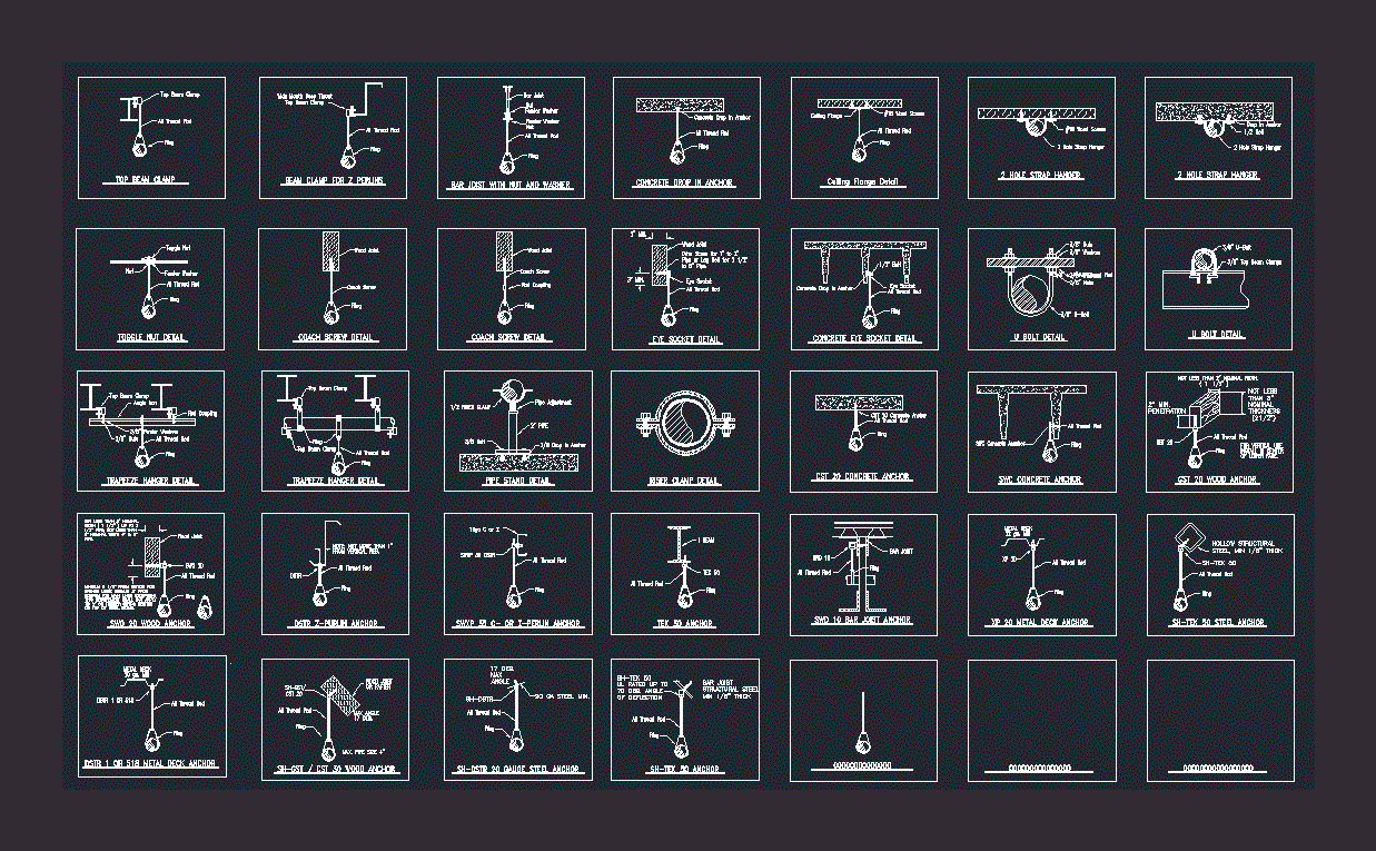
Drainage DWG Detail for AutoCAD
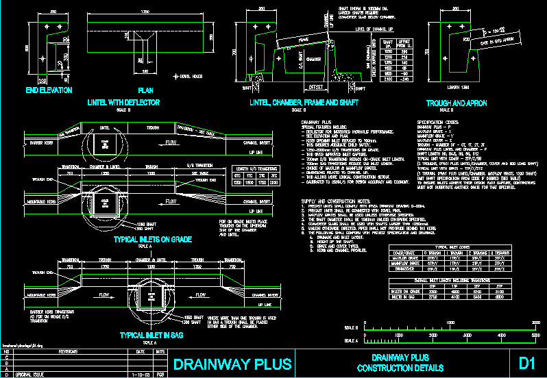
Drainage – construction details
Drawing labels, details, and other text information extracted from the CAD file:
frame and shaft, end elevation, lintel with deflector, plan, shaft, dowel holes, chamber, frame, length, trough and apron, check supplied units, shaft, shaft shown is dia. larger shafts require converter slab below chamber., level of channel lip, shaft, lip line, channel, dia, from ll., offset, cast in situ apron, lintel, lintel, transition, table, prod of cal.dwg, shaft offset dia, frame, channel lip line, stormway, revisions, original issue, pgb, inits, date, chamber lintel, trough, chamber lintel, trough, trough, drainway plus construction details, typical inlets on grade, typical inlet in sag, flow, trough end, lip line, channel invert, lip line, shaft, cover or grate, scale, scale, scale, typical inlet codes, trough, troughs, draincover, mannflow grate, maxflow grate, where more than one trough is used in sag trough shall be placed either side of the chamber., transition, transition, trough end, transition, see table, drainway plus features include: deflector for increased hydraulic performance. see elevation and plan. kerb opening inlet reduced to this ensures adequate child safety. transitions on grade. this gives improved inlet capture. transitions reduce inlet length. sag transitions reduce sag inlet length. choice of maxflow mannflow grates. dimensions related to channel lip. this allows more logical construction setout. calibrated to for design accuracy and economy., supply and construction precast units shall comply with ipwea drainway drawing precast units shall be connected with dowel pins. maxflow grates shall be used unless otherwise specified. the shaft diameter shall be unless otherwise specified. converter slabs shall be used with shafts larger than unless otherwise pipes shall not protrude behind the kerb. the following shall conform with project specification and drawings. a. drainage and inlet layout. b. height of the shaft. c. grate and cover types. d. kerb and channel profiles., specification drainway plus maxflow grate mannflow grate maxflow cover trough number of drainway plus lintel and chamber shaft length typical unit with cover d’way plus cover and long typical unit with grate d’way plus maxflow omit shaft specification from code if desired to ensure inlets achieve their design flow contractors must not substitute another grate for that specified., flow, channel invert, lip line, barrier kerb, mountable kerb, lintel, trough, mountable kerb, barrier kerb transitions as for on grade transition, transition, transition see table, cover or grate, length transitions, otc, inlets in sag, inlets on grade, overall inlet length including transitions, for on grade inlets place troughs on the upstream side of the chamber and lintel., shaft, drainway plus
Raw text data extracted from CAD file:
| Language | English |
| Drawing Type | Detail |
| Category | Water Sewage & Electricity Infrastructure |
| Additional Screenshots |
 |
| File Type | dwg |
| Materials | Other |
| Measurement Units | |
| Footprint Area | |
| Building Features | |
| Tags | autocad, construction, DETAIL, details, drainage, DWG, kläranlage, treatment plant |
