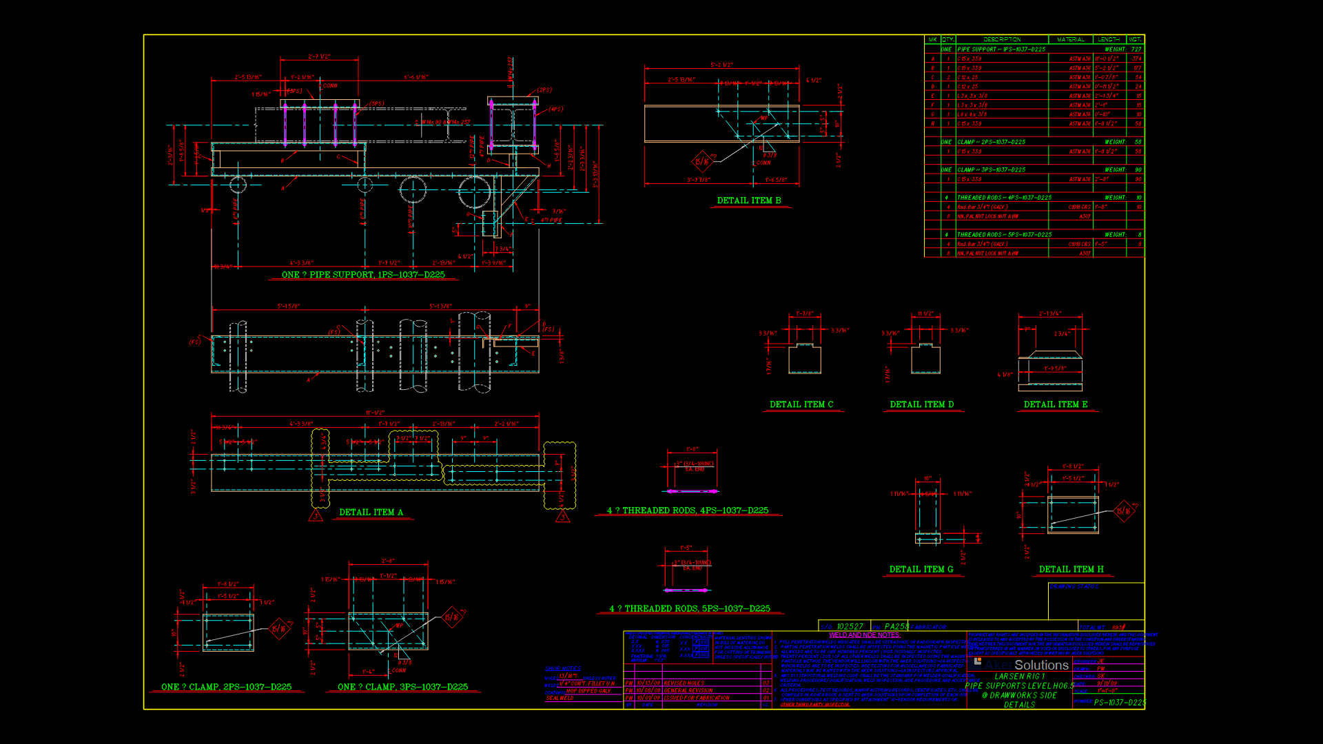
Horizontal Shell and Tube Heat Exchanger Assembly Detail

This drawing depicts a detailed side elevation and end view of an industrial horizontal shell and tube heat exchanger. This cylindrical pressure vessel features multiple support saddles indicated by the magenta foundation blocks. Internal components include tube bundles with inlet/outlet connections and what appears to be a floating head design for thermal expansion accommodation. The shell diameter is approximately 1000mm with an overall length of roughly 4500mm based on proportional analysis. The drawing incorporates both the main exchanger body and mounting supports, with clear delineation of access points for maintenance. The design follows typical TEMA (Tubular Exchanger Manufacturers Association) standards with visible nozzle connections and reinforcement pads at the shell penetrations. Particular attention has been given to the support structure interface; the foundation footprint suggests this unit is designed for permanent installation in an industrial process environment.
| Language | English |
| Drawing Type | Elevation |
| Category | Industrial |
| Additional Screenshots | |
| File Type | dwg |
| Materials | Steel |
| Measurement Units | Metric |
| Footprint Area | 10 - 49 m² (107.6 - 527.4 ft²) |
| Building Features | |
| Tags | heat exchanger, hvac, pressure vessel, process equipment, shell and tube, TEMA, thermal |
Related Products


Same Contributor

Featured Products


