Industrial Process Flow Section Drawing for Manufacturing Plant
Industrial Process Flow Schematic Overview
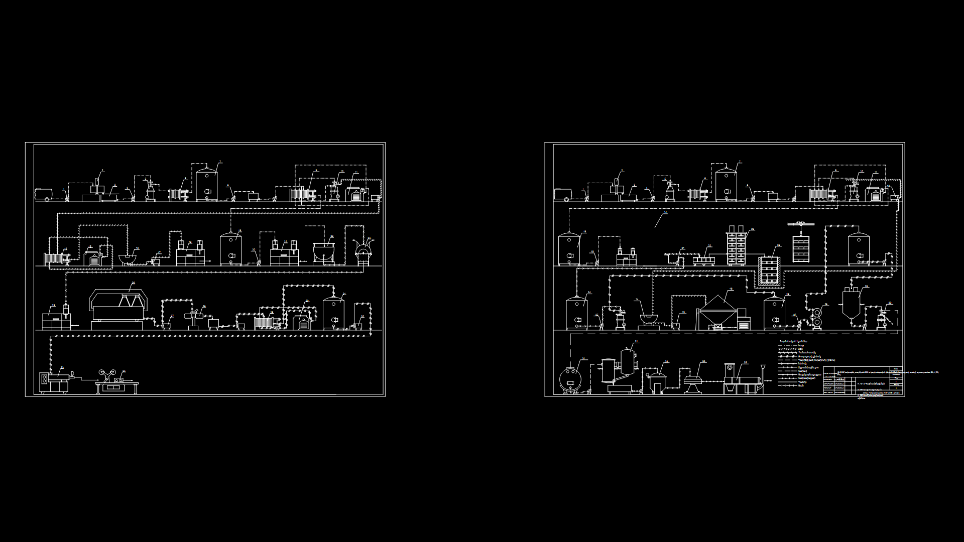
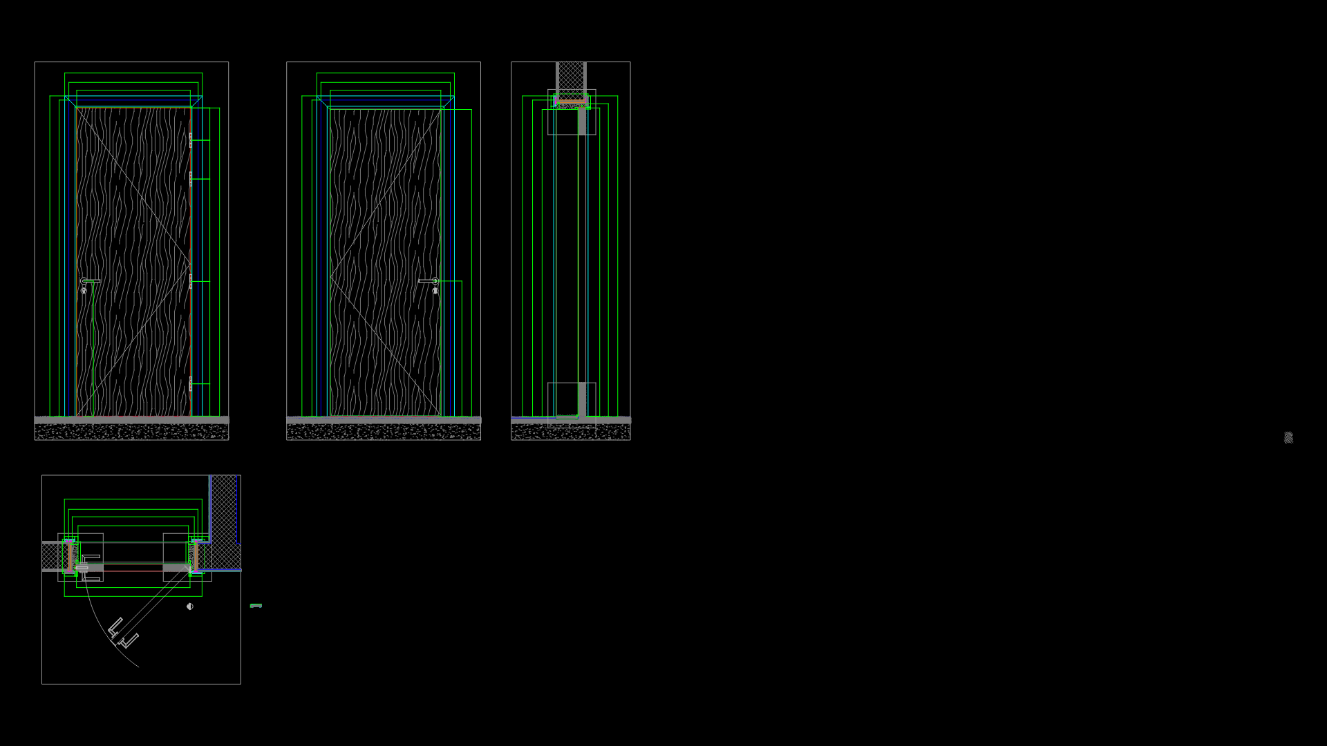
This technical section drawing depicts a comprehensive industrial process flow system with multiple levels of manufacturing equipment and processing units. The schematic illustrates a multi-tiered production facility with interconnected processing stations and storage tanks.
Key Process Elements:
– Multiple vertical levels showing different stages of the manufacturing process
– Storage vessels and tanks of varying dimensions connected via piping networks
– Processing equipment including what appears to be centrifuges, mixers, and reactor vessels
– Material handling systems with designated flow directions
– Thermal processing units integrated into the production line
– Quality control or testing stations at strategic points
The drawing employs standard industrial symbology for process equipment with flow direction indicators and connection points clearly marked. Equipment is arranged in a logical sequence that follows material transformation through various, overall, processing stages. The sectional view provides critical insights into the vertical relationships between different process components, enabling engineers to understand both spatial requirements and gravitational flow dynamics.
Process integration appears to be optimized for efficient material transfer between stages, with consideration for maintenance access and operational safety requirements.
| Language | Other |
| Drawing Type | Section |
| Category | Industrial |
| Additional Screenshots | |
| File Type | dwg |
| Materials | Steel |
| Measurement Units | Metric |
| Footprint Area | 500 - 999 m² (5382.0 - 10753.1 ft²) |
| Building Features | |
| Tags | chemical processing, industrial plant section, manufacturing equipment, plant layout, process engineering, process flow diagram, production line |
Related Products
Same Contributor
Featured Products


