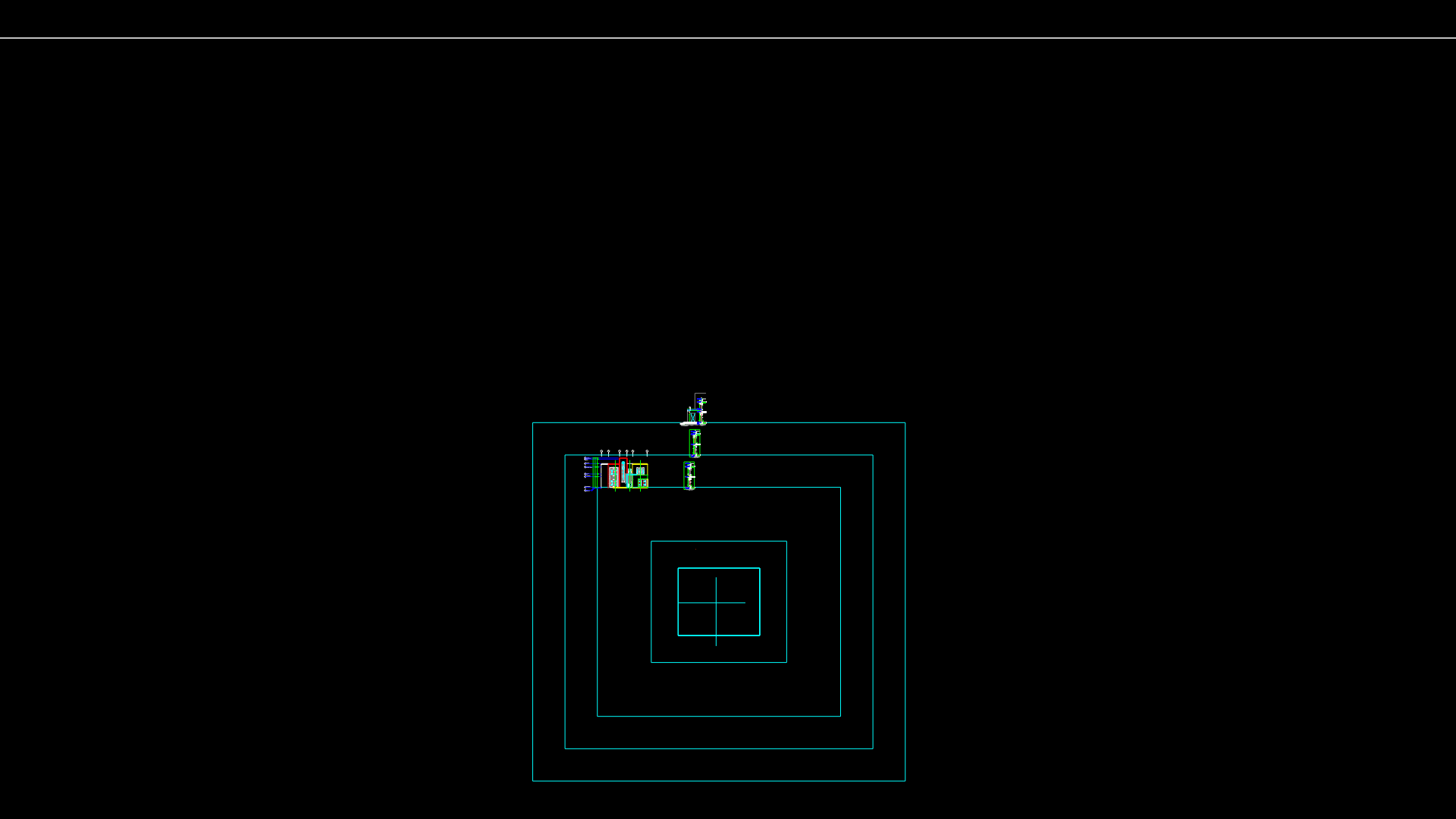
Mechanical component Plan with Circular Ports and Cavity Detail
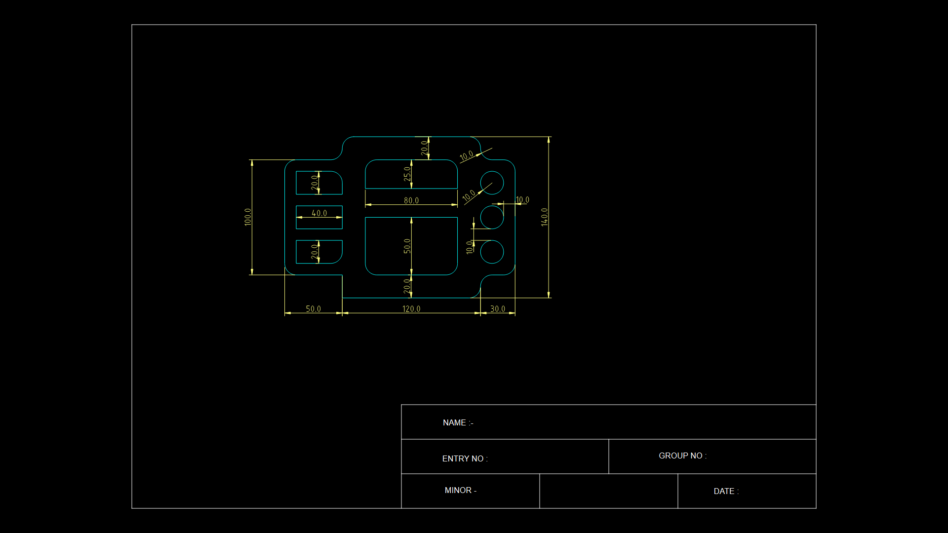
This technical drawing depicts a precision mechanical component with multiple features including a central square cavity (50mm x 50mm) and three circular ports (10mm diameter) aligned on the right side of the component. This overall dimensions are 200mm x 140mm, with a complex rounded-corner profile. The main body features an 80mm width central section with smaller 20mm and 40mm features on the left side. The drawing utilizes LWPOLYLINE entities for the outline with properly dimensioned features using the metric system. All critical dimensions are labeled, including the 120mm central section width and 30mm edge dimensions. The component appears to be designed for a specific mechanical interface, possibly for educational purposes as suggested by the form fields for name, group number, and entry number at the bottom of the drawing.
| Language | English |
| Drawing Type | Detail |
| Category | Mechanical, Electrical & Plumbing (MEP) |
| Additional Screenshots | |
| File Type | dwg |
| Materials | |
| Measurement Units | Metric |
| Footprint Area | 1 - 9 m² (10.8 - 96.9 ft²) |
| Building Features | |
| Tags | cavity detail, circular ports, component interface, Engineering Drawing, mechanical component, precision machining, technical drawing |
Related Products
Same Contributor

Featured Products


