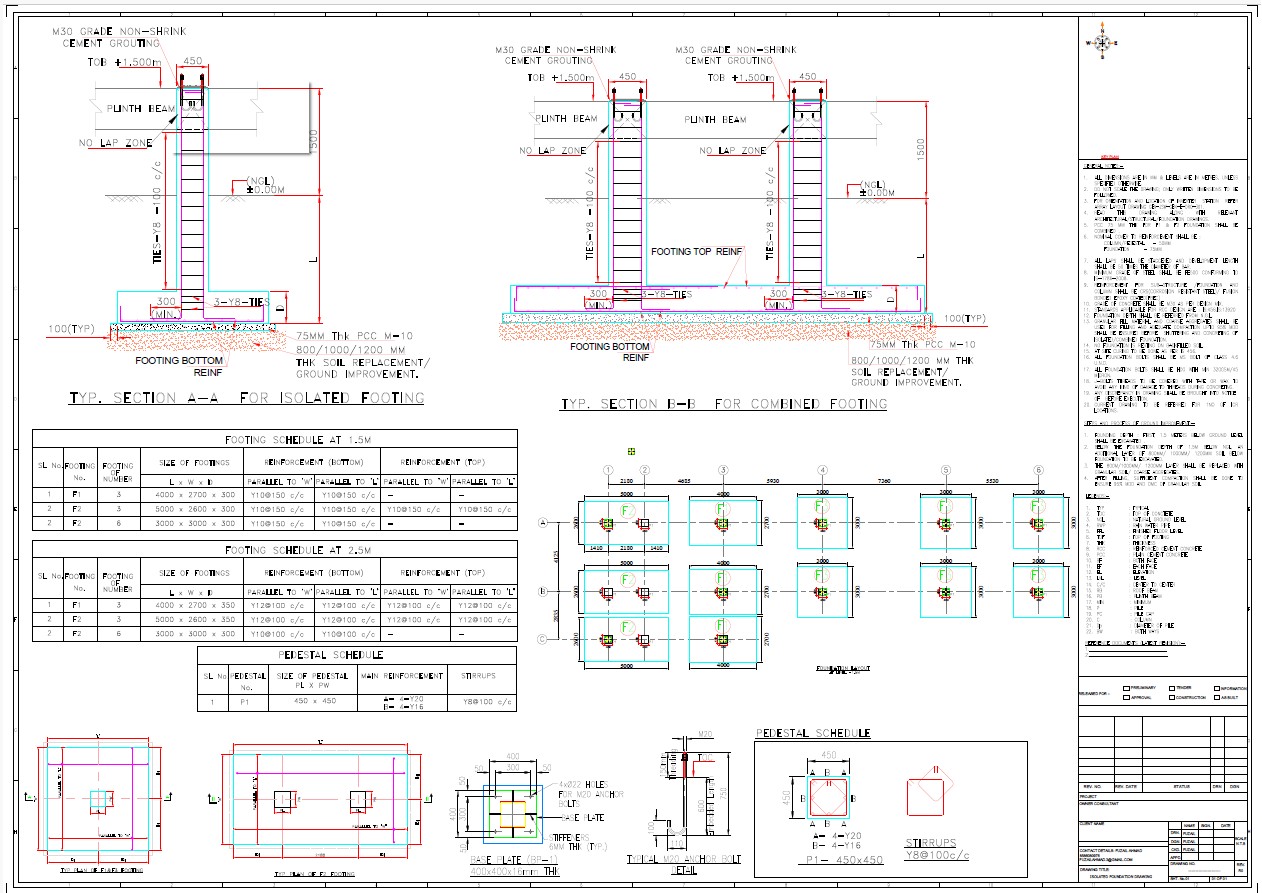
NIFPS PANEL FOUNDATION DRAWING
The foundation drawing of an NIFPS provides a detailed layout of the system’s structural base, including:
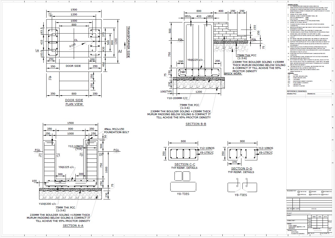
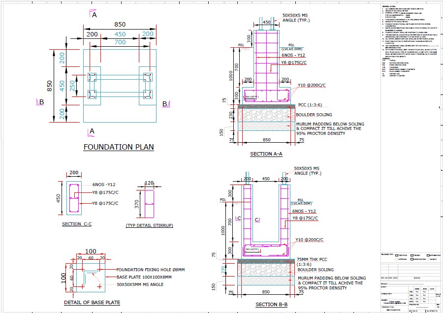
Foundation Dimensions & Layout
Specifies the size, depth, and reinforcement details of the foundation to support NIFPS equipment.
Includes anchor bolt positioning and load-bearing capacities.
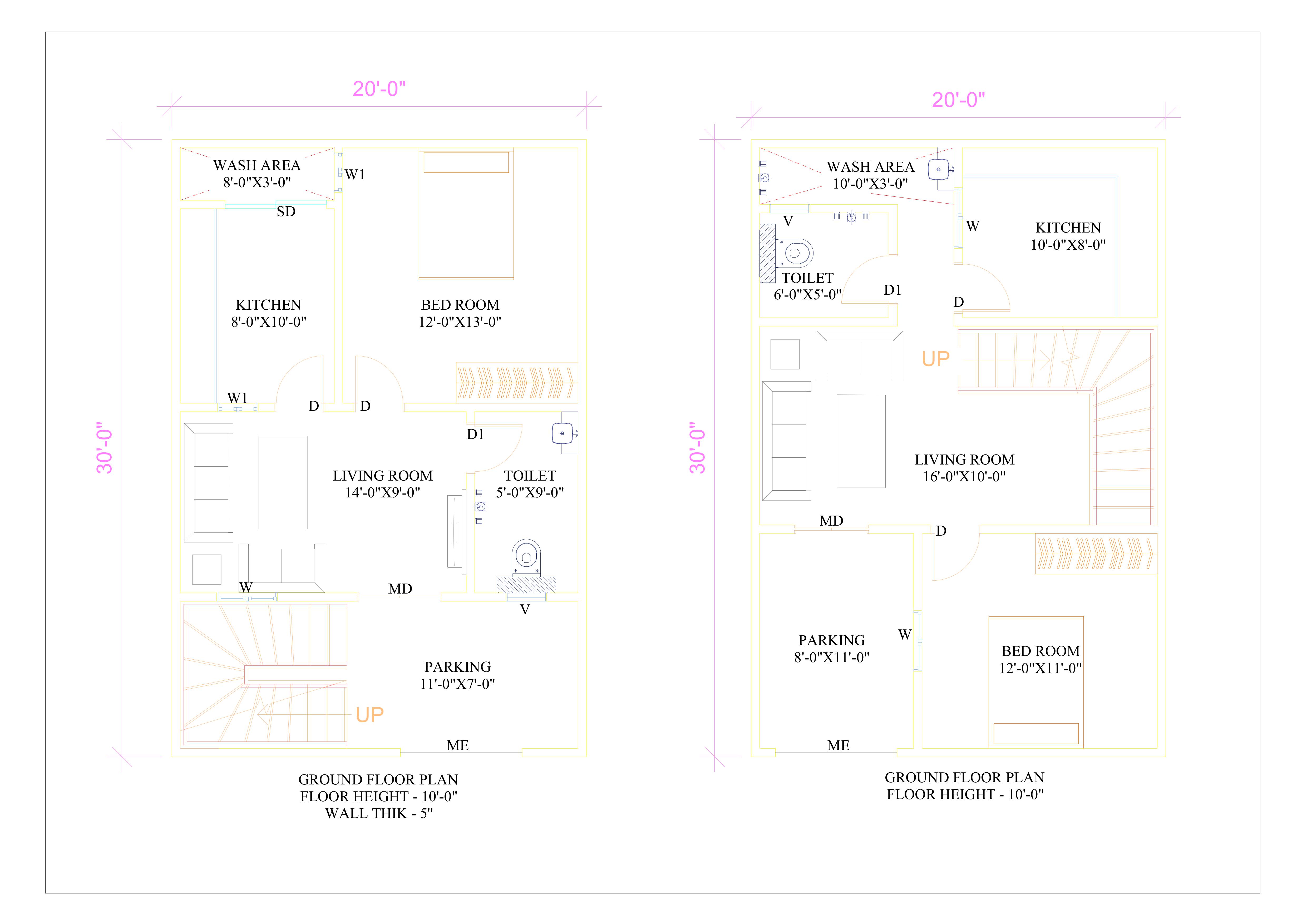
Equipment Placement
Shows designated areas for nitrogen storage cylinders, control panels, and piping connections.
Ensures proper spacing for accessibility and maintenance.
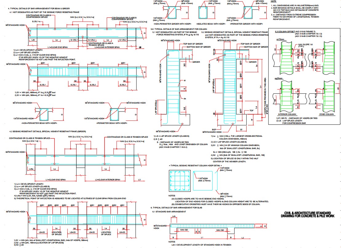
Structural & Civil Details
Depicts concrete slab thickness, reinforcement bars, and grounding requirements.
Incorporates seismic and wind load considerations if applicable.
Piping & Conduit Pathways
Indicates the routing of nitrogen supply lines, control wiring, and exhaust outlets.
Ensures proper integration with the transformer and fire detection systems.
Mounting & Support Details
Provides specifications for brackets, supports, and securing mechanisms for equipment stability.
This foundation drawing serves as a critical reference for engineers, contractors, and safety regulators to ensure proper installation and structural integrity of the NIFPS.
| Language | English |
| Drawing Type | Detail |
| Category | Building Codes & Standards |
| Additional Screenshots | |
| File Type | Array |
| Materials | Concrete, Steel |
| Measurement Units | Metric |
| Footprint Area | 50 - 149 m² (538.2 - 1603.8 ft²) |
| Building Features | Fireplace, Garage |
| Tags | BULIDING, civil, construction, footing, FOUNDATION, NIFPS, PLINT BEAM, rcc, slab |
Related Products
Same Contributor
Featured Products


