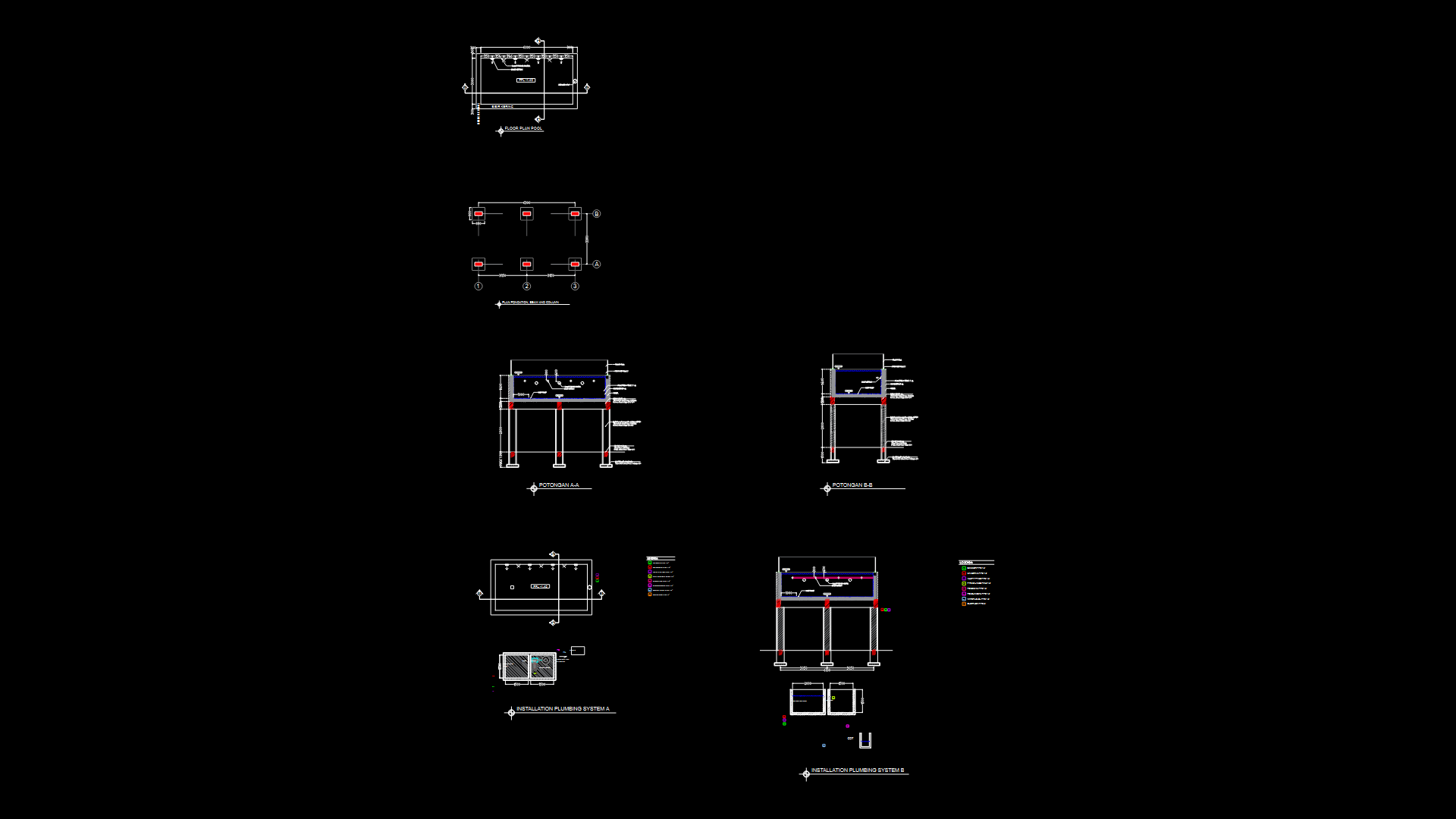
Pool’s Details DWG Detail for AutoCAD
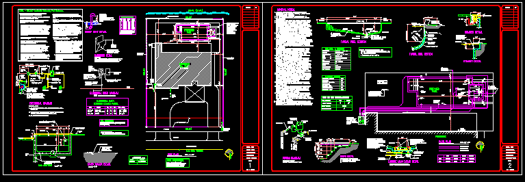
Planes of pool – Electrical Raiser Diagram – Piping diagram
Drawing labels, details, and other text information extracted from the CAD file:
utility easement, line, existing, san., north, p.o.e., step, light, seat, brick paver detail, scale, conc. edge curb, layer of well, compacted limerock, over sand fill, pervious brick pavers, soil condition at site by visual inspection indicates an, allowable bearing capacity of p.s.f., sand rock, soil statement, outlet to maximum of in of, transmission of suction at the, the vent system is to limit the, mercury, relief vent detail, above grade, with goose neck, vent pipe, grade, these vent system will limit the, transmission of suction at the, outlet to maximum of of, mercury in water column, vent pipe schedule, vent, size, gpm, pump, h.p., rate, flow, l.f., maximum, length, min., anchor bolts, pool equipment, on concrete pad, and secured with, with nuts and washers, handhold detail, feet at any two points, within feet not to exceed, ceramic tile handhold at, maximum, above from, water level, handholds shall be accessible within feet not to, exceed feet at any two points along the inside of the, pool perimeter where the water depth exceeds feet, with f.b.c. ansi, water velocity to comply, in compliance with the and fbc and all applicable, joints spaced at o.c. or for an effective concrete area of sq. ft., crack control joints shall be sawcut at depth of the slab thickness., concrete pool shall be provided wide sawcut crack control, local codes and regulations., patios are indicated by others. the patio desing notes, shown on the typical wall section do not apply. patio design, to empty pool after construction for repairs or any, experienced in eliminating uplift pressures., upward. the owner must consult and pool repair contractor, pool must be eliminated to prevent the pool from floating, our professional knowledge and they have been prepared, written permission of the design engineer and to the best of, not transferable from one contractor to another without the, this plans remains the property of the design engineer. it is, other the hydrostatic uplift pressures beneath the, patio shall be placed in similar manner., high is fence recommended around all pools in, unscreened areas. comply with chapter of the f.b.c., the notify the engineer for instructions., repaired. continual maintenance of the walls is required of the, fully contain the soils behind they shall be replaced or, conditions not permitting any shifting or removal or loosening, special care shall be employed. the walls shall be in good, tiebacks shall not be cut. where concrete deadmen fall within, property owner. when excavating for the the seawall, of the supporting soil away from the pool. if the walls do not, with clean sands free of organic materials and shall be placed, plumbing shall not be disturbed. backfill shall be accomplished, the soils maximum density by tamping solidly. soils below the, in thick layers. each layer shall be compacted to of, contractor shall backfill the pool shell with caution. the, pools abut or are placed nearby seawalls or bulkheads, all floors and walls of pool to be concrete shall be, all reinforcing steel to conform to astm grade, shall be removed in their entirety and the ar
Raw text data extracted from CAD file:
| Language | English |
| Drawing Type | Detail |
| Category | Pools & Swimming Pools |
| Additional Screenshots |
 |
| File Type | dwg |
| Materials | Concrete, Glass, Masonry, Steel, Wood, Other |
| Measurement Units | |
| Footprint Area | |
| Building Features | Pool, Deck / Patio, Car Parking Lot, Garden / Park |
| Tags | autocad, DETAIL, details, diagram, DWG, electrical, piping, piscina, piscine, PLANES, POOL, schwimmbad, swimming pool |
