Reinforcement Details for Columns and Walls from +3.20 to +6.20 Level
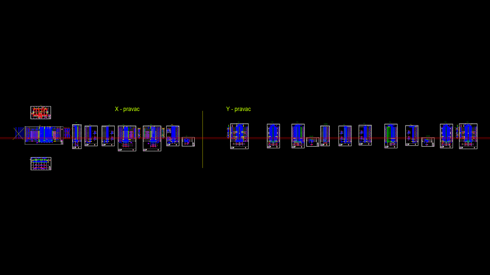
Structural reinforcement drawing showing detailed vertical reinforcement arrangements for concrete columns and walls between elevations +3.20m and +6.20m in a multi-story building. The drawing displays multiple column and wall sections with precise rebar positioning, dimensions, and connection details. Layout is organized along X and Y grid axes (‘X-pravac’ and ‘Y-pravac’), providing clear reference for construction implementation. The drawing includes specific rebar schedules, material specifications, and sectional views with reinforcement configurations, in essence, optimized for lateral load resistance. Critical column-wall junctions are detailed with reinforcement overlap requirements and dimensional specifications conforming to structural engineering standards for reinforced concrete construction.
| Language | Arabic |
| Drawing Type | Detail |
| Category | Construction Details & Systems |
| Additional Screenshots | |
| File Type | dwg |
| Materials | Concrete, Steel |
| Measurement Units | Metric |
| Footprint Area | 1000 - 2499 m² (10763.9 - 26899.0 ft²) |
| Building Features | |
| Tags | concrete columns, rebar detailing, reinforced concrete, structural engineering, structural reinforcement, vertical reinforcement, wall reinforcement |
Related Products


Same Contributor


Featured Products


