Structural Steel building Plan with Base Plate & Connection Details

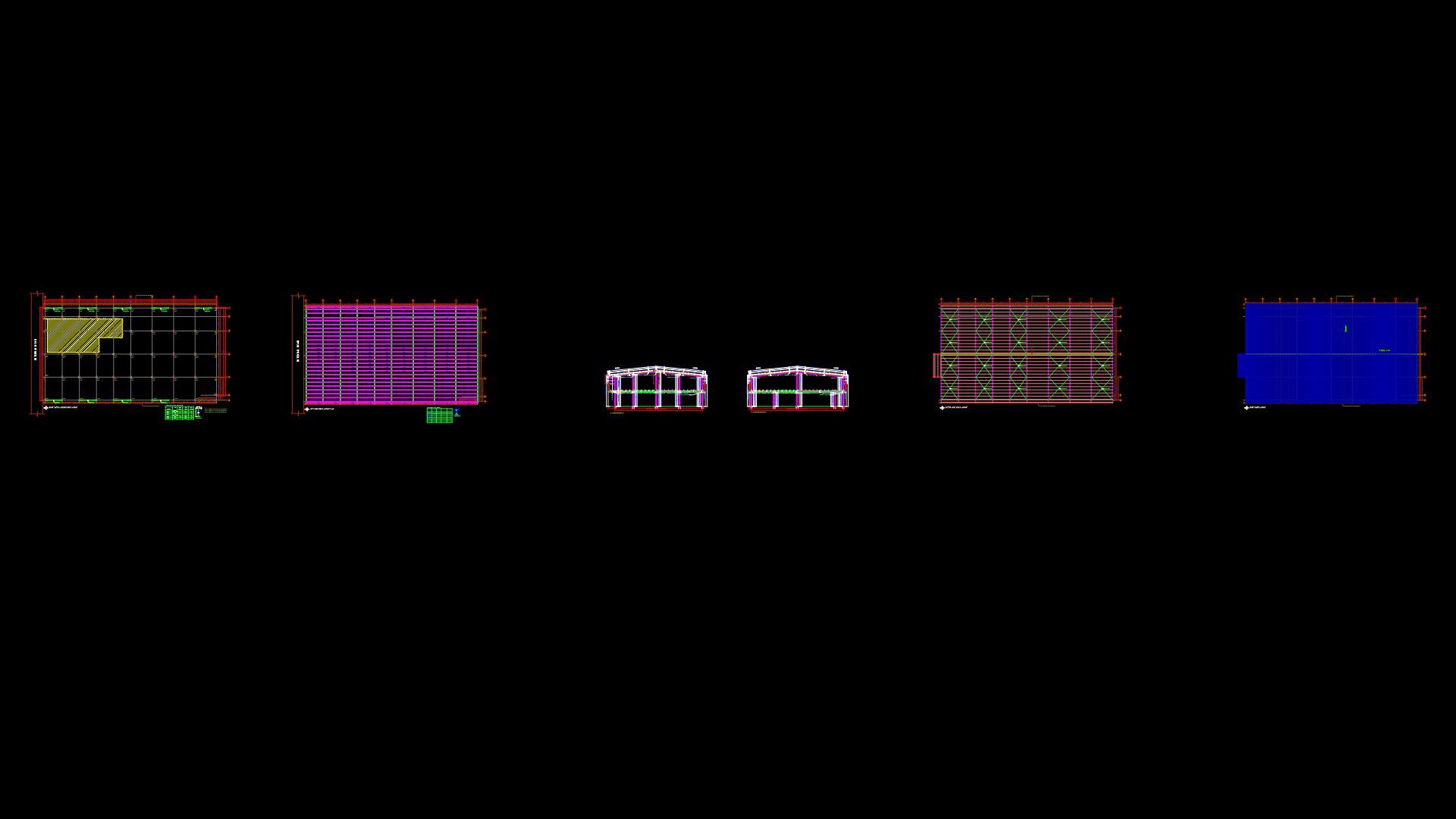
This comprehensive structural steel building drawing depicts a framed industrial facility with clear spans of approximately 57m. The drawing features detailed base plate layouts with 12-20mm anchor bolts (BP-1, BP-2, BP-3), steel column configuration, and beam connection details. Primary steel sections include built-up columns (175×8mm flanges with 300×5-6mm webs) with clear heights ranging from 4500mm to 11385mm. The roof structure includes a series of rafters (marked R1-R3) with integrated purlin layout and cross-bracing for lateral stability. Main beams (MB-01 through MB-04) and tie beams (TB-01, TB-02) are fully scheduled with web and flange dimensions. Several structural sections showcase connection points between the steel frame and existing RCC columns. The drawing utilizes a grid system for dimensional reference, with specific section cuts showing crucial interface details at key grid intersections. The purlin spacing and roof sheeting system is integrated with the primary structural frame, accommodating proper water drainage along the ridge line.
| Language | English |
| Drawing Type | Full Project |
| Category | Industrial |
| Additional Screenshots |
 |
| File Type | dwg |
| Materials | Concrete, Steel |
| Measurement Units | Metric |
| Footprint Area | 1000 - 2499 m² (10763.9 - 26899.0 ft²) |
| Building Features | |
| Tags | base plate details, built-up sections, cross bracing, industrial building, portal frame, steel structure, structural connections |


