3D Industrial Conveyor System Model with Roller Mechanism

Industrial Conveyor System Assembly
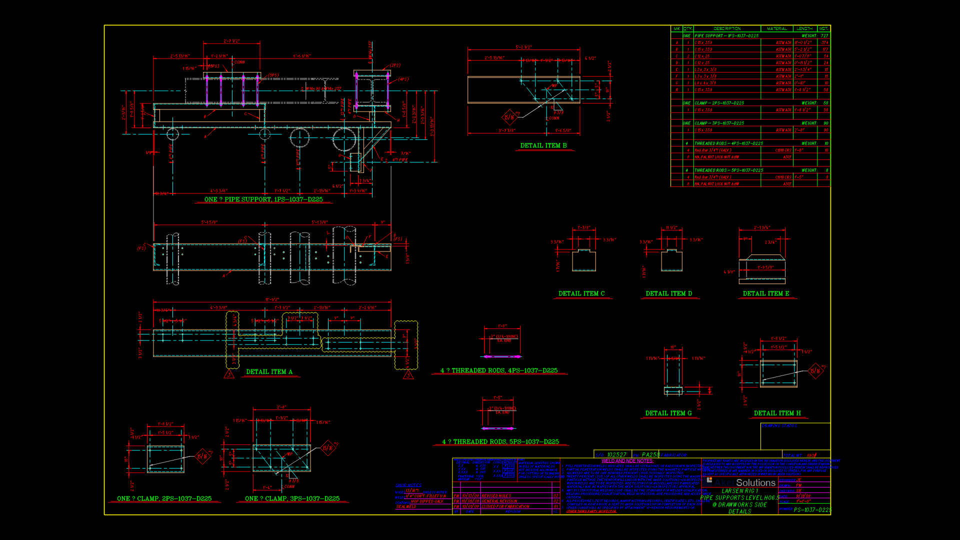
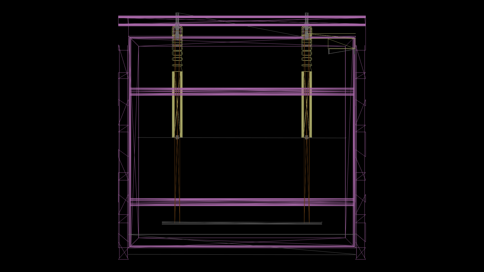
This technical drawing depicts a detailed 3D model of an industrial conveyor system component, specifically a roller-based transfer mechanism. The assembly features a rectangular frame structure with integrated support legs and mounting brackets positioned at strategic locations for optimal load distribution.
The core component appears to be a central roller mechanism with bearing housings mounted at four corner positions, enabling smooth rotational movement. The cylindrical roller element (visible on the right side) is designed for material transfer applications in manufacturing or processing environments.
Key Technical Features:
* Frame assembly with reinforced structural members
* Four bearing mounting points with standardized bolt patterns
* Central drive shaft connection point at the bottom assembly
* Cylindrical roller element with proper clearance for material handling
* Support structure designed for floor or platform mounting
The model’s construction suggests steel fabrication with welded and bolted connections, typical for industrial material handling equipment. The design demonstrates practical considerations for maintenance access, with bearing assemblies positioned for easy replacement during scheduled maintenance intervals.
| Language | English |
| Drawing Type | Model |
| Category | Industrial |
| Additional Screenshots | |
| File Type | dwg |
| Materials | Steel |
| Measurement Units | Metric |
| Footprint Area | 1 - 9 m² (10.8 - 96.9 ft²) |
| Building Features | |
| Tags | 3D CAD model, bearing assembly, conveyor system, Industrial Equipment, machine component, material handling, roller mechanism |
Related Products


Same Contributor
Featured Products


