4-Cylinder Internal combustion Engine Assembly Technical Drawing
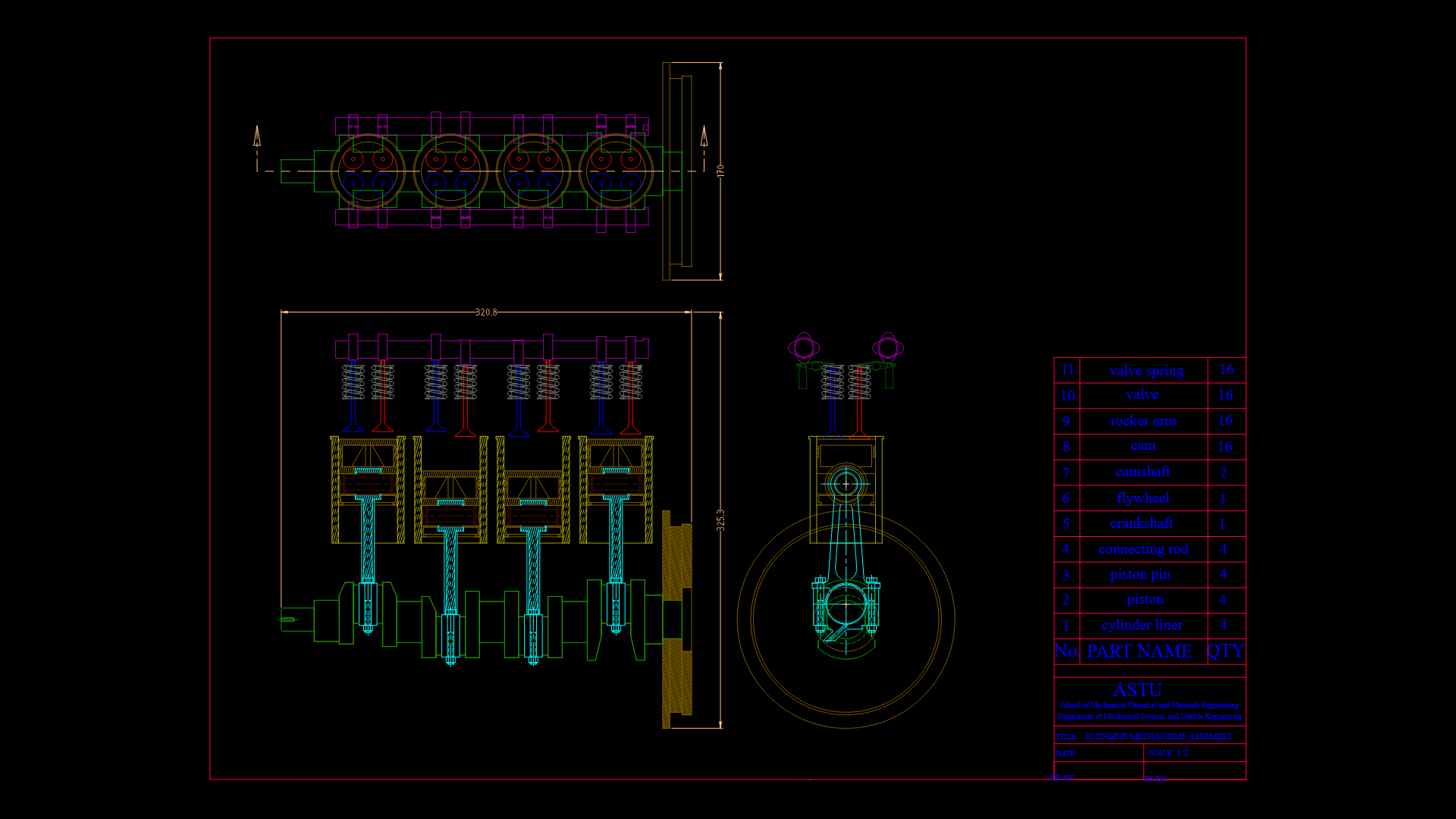
This detailed technical drawing depicts a complete internal combustion engine assembly shown in multiple views. The engine features four cylinders arranged in-line with dimensions of approximately 320.8mm in length. Key components are organized in dedicated layers including pistons, connecting rods, crankshaft, camshaft, valves with springs, and rocker arms – all critical to the engine’s operation. The drawing illustrates the power conversion mechanism from linear piston movement through connecting rods to rotational motion via the crankshaft. The valvetrain system shows the relationship between camshaft, rocker arms, and valves with springs. Of particular engineering significance is the clear representation of how these components interact during the engine cycle. The assembly uses a traditional flywheel to maintain rotational momentum between power strokes. Component quantities are specified in the parts list: 4 cylinder liners, 4 pistons, 4 piston pins, 4 connecting rods, 1 crankshaft, 1 flywheel, 1 camshaft, 6 cams, 16 rocker arms, 16 valves, and 16 valve springs. The functional clearances between moving components appear to follow standard automotive engineering tolerances, though specific clearance values aren’t dimensioned.
| Language | English |
| Drawing Type | Model |
| Category | Mechanical, Electrical & Plumbing (MEP) |
| Additional Screenshots | |
| File Type | dwg |
| Materials | Aluminum, Steel |
| Measurement Units | Metric |
| Footprint Area | N/A |
| Building Features | |
| Tags | CAMSHAFT, crankshaft, engine assembly, four-cylinder, internal combustion engine, mechanical engineering, piston assembly, valvetrain |
Related Products


Same Contributor


Featured Products


