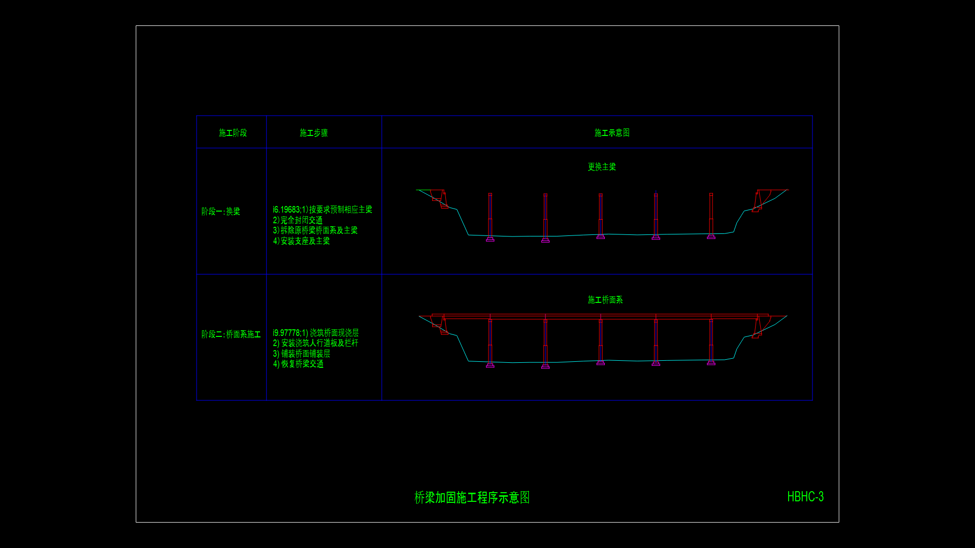
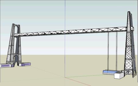
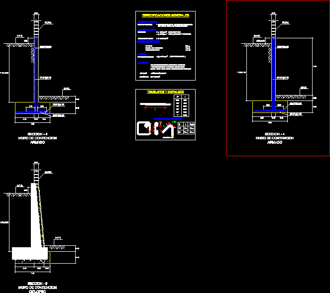
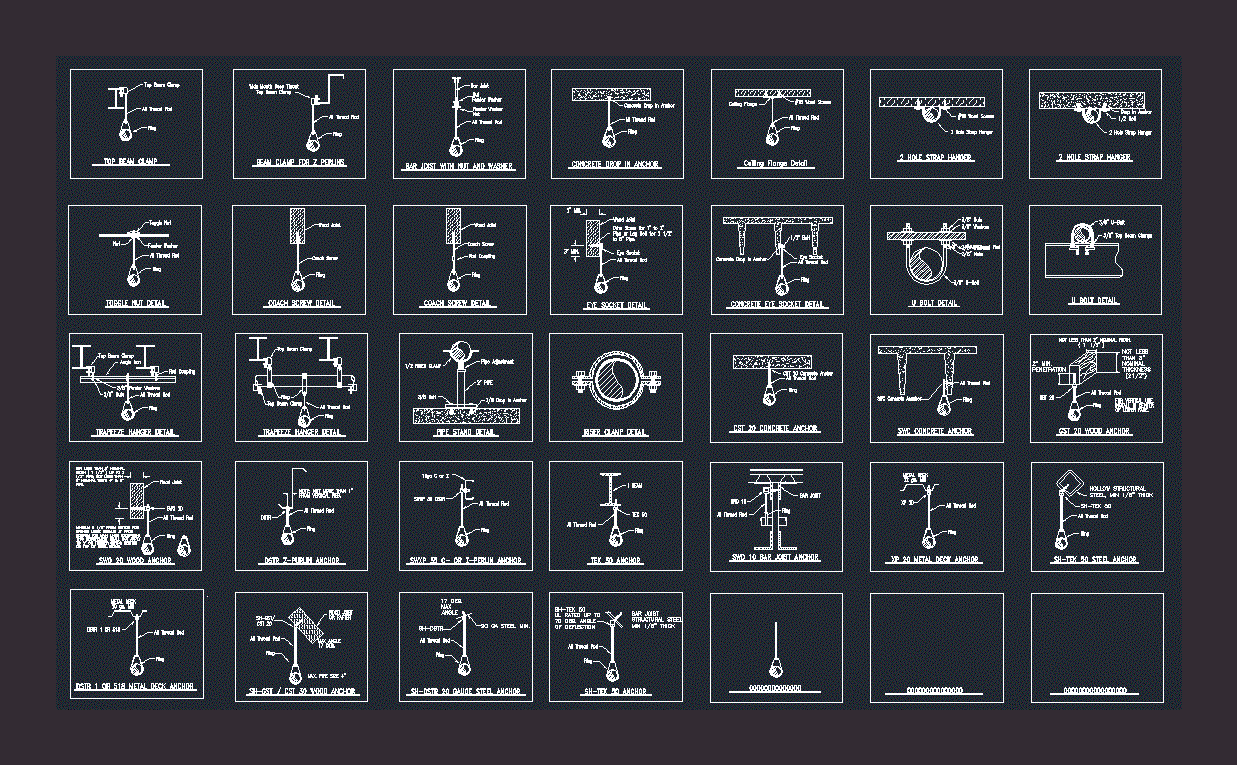
Bridge Beam-Flagstone Of 100mts DWG Detail for AutoCAD

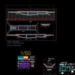
Complete bridge with details of structure and super-structure
Drawing labels, details, and other text information extracted from the CAD file (Translated from Spanish):
nm, cut aa, diaphragm, beam, main beam, sidewalk, road, welded to the angle, slab – bridge, screen – abutment, joint detail, welded to the angle after bolting, asphalt, trunk detail, mobile support, support, abutment, shaft, see joint, slab, neoprene support, upper bar, no scale, lower bar, development length, bar, lower, upper, elevation, terrain, subgrade, mileage, v. d., direction of traffic, rolling surface, beam diaphragm, longitudinal profile, scale :, superstructure plant, bb cut, cross section of the bridge, iron detail, cross section, exterior, structural detail of reinforced slab, plant, steel layer upper, steel lower layer, armor section outer beam, light center, beam cut, interior, section, critical, thickness, cantilever detail, granular material base, a-a cut, support area for the approaching crockery, support metallic neoprene, neoprene, pipe, late-winged wings, pillar plant, plate, pillar lift, pillar profile, pillar isimetry, stapes floor, stapes lift, – the quality of the reinforcement steel shall not exceed what is specified for arn grade steel, – the splices should be made only as required or allow the design plans, – the overlapping splices of the reinforcement in areas of stress inversion, should remain, – splices should not be made t raslapados or soldiers in the reinforcement within an area, beam on each side., technical specifications or as authorized by the inspector., – the sites may be of different types :, shall be treated as an element in flexocompresión., – beams that must be resist earthquake forces shall comply with what is indicated in this, overlapping splices of corrugated bars, – the minimum length of a splice overlapped in compression shall be the length of development in, within a required length of overlap type c splice shall be used. , required overlap type b splices should be used. if more than half of the ba- is joined, strictly necessary and if less than half of the bars are spliced within one length, – splices in areas of high stress should preferably be avoided, however, if they were, where is the length of the splice, and ld is the length of development in traction., – the minimum length of the overlap in the splices overlapped in traction will be in accordance with the re, package should not coincide within the same overlap length., – the bars spliced by means of overlaps are contact in elements subjected to bending, no, – the overlaps of bars forming packages must be based on the required overlap length, section for the design of the longitudinal steel., splices in the reinforcement, subject to comprehension, subject to traction, splices by overlap, long. desar in cm., values, internal reinforcement, h any, length, of the hook, c.- for lightened and flat beams, steel, specified, increase the length of joint, indicated or with the percentages, b.- in case of do not join in the zones, in the same section, note, interior is spliced on the supports, resist. comp. masonry, max size aggregates, diam. min.doblado stirrups, technical specifications, f’c, lower bars, concrete walls, steel, concrete columns, lightened concrete, concrete beams, for traction bars, development lengths, upper bars, longitudinal profile, superstructure, -transverse section, architecture, details
Raw text data extracted from CAD file:
| Language | Spanish |
| Drawing Type | Detail |
| Category | Roads, Bridges and Dams |
| Additional Screenshots |
 |
| File Type | dwg |
| Materials | Concrete, Masonry, Steel, Other |
| Measurement Units | Metric |
| Footprint Area | |
| Building Features | |
| Tags | autocad, bridge, complete, DETAIL, details, DWG, mts, structure |


