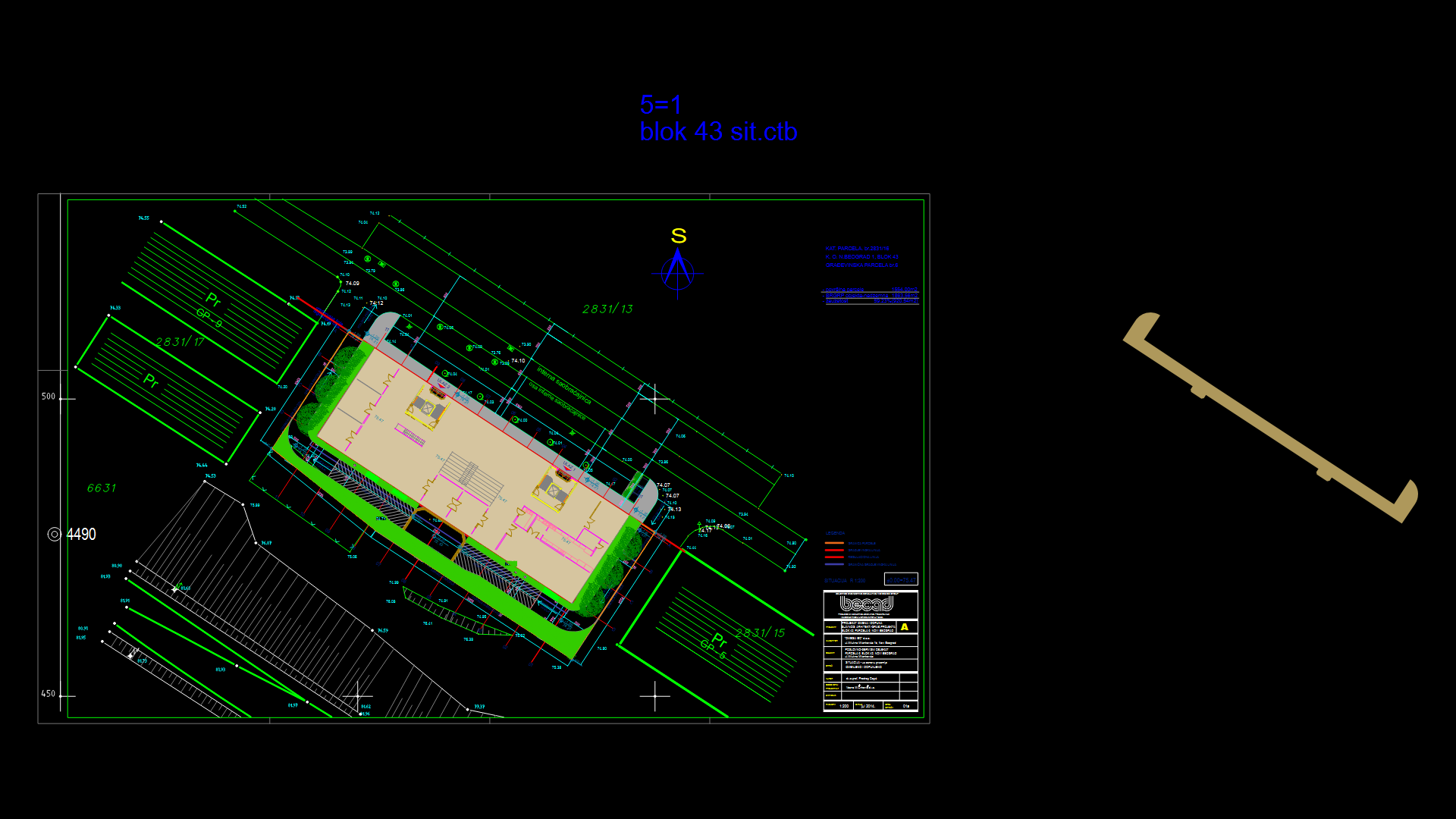
Commercial Call Center Upper Roof Plan with Drainage System

This architectural drawing depicts the upper roof plan for a call center building, presenting a comprehensive drainage system with 1% slope gradients. The roof features multiple roof drains (J.R. Smith 1005 series) strategically positioned to facilitate water runoff along specified directional slopes. Access elements include two 800x800mm floor access hatches and metal wall ladders with safety cages for maintenance accessibility. Elevation markers indicate the Top of Concrete (TOC) at 112.900m with additional elevation points at 111.600m and 107.900m. The structural grid utilizes a combination of 200x200mm and 400x700mm concrete columns supporting the roof system. The drawing includes multiple section cuts (referenced as AE201, AE301, AE311) that provide detailed construction information at critical junctions. The entire layout demonstrates practical consideration for water management through carefully planned slope directions and drainage points, essential for preventing water pooling and ensuring the long-term integrity of the roofing system.
| Language | English |
| Drawing Type | Plan |
| Category | Commercial |
| Additional Screenshots | |
| File Type | dwg |
| Materials | Concrete |
| Measurement Units | Metric |
| Footprint Area | 1000 - 2499 m² (10763.9 - 26899.0 ft²) |
| Building Features | |
| Tags | access hatches, BIM, Commercial Building, roof drainage, roof plan, slope design, waterproofing |
Related Products


Same Contributor


Featured Products


