Expansion Joints Illustrated DWG Section for AutoCAD

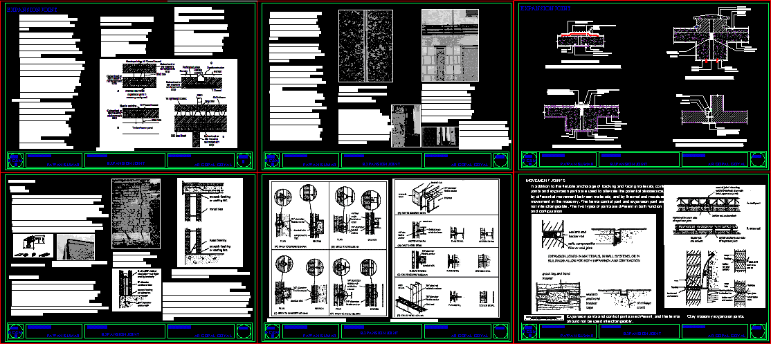
Expansion joint details in buildings; types; sections.
Drawing labels, details, and other text information extracted from the CAD file:
kerc half battered, kerb beam, channel detail, anchor bolts as, recommended by, manufaturer, min pvc, pole, double nut lock washer, expansion joint, r bars for vertical ties, section electric light fixing, kerb detail, fixed, chained, stopper, plug, mortor fillet, gully frame beded on, flexible joint, concrete gully, road gully detail, fixed chained stopper, compressible, joint filler, plan scale, building, footpath, carrige way, sub base, drive way, section at b-b’, bicycle, track, foot, path, vehicular, road, base, road way, section at a-a’, typical section, electric pole, green area, sidewalk, property line, first layer of bitumen, rcc slab on roof surface, felt free erom base, bitumen felt, gravel, bitumen, rcc coping, bitumen painting, mud fuska, brick tiles, rcc slab, ceiling plaster, metal cradle, rawl plug with, ovel shaped slot, a.c. sheet, rcc beam, filled up with, bitumen filler, sepration joint detail at roof, typical detail of sepration or crumple section, flat asbastos cement sheet, or plywood or any other, equally suitable meterial, steel or, metal sheet, aluminium angle, expansion joint using steel or aluminium angles, gap, ovel shaped slot and washer, plaster, to match the floor finesh and, laid over a coat of hot bitumen, floor, rawl plug and scerews, rcc beam, typical detail of expansion joint in walls, typical detail of expansion joint at floor, metal, cradle filled up with, sheet, submitted to:-, ar.gopal goyal, sheet title:-, submitted by:-, pawan kumar, sub:-, sheet metal flasing, fragile cover, metal trim, brick walls, mastic, anchor bars, welded, flats, clear, concrete walls, flat bar set in forms, fastening, exterior, sheet cover panel, girts, wf column, sepration at floor level, sheet metal flashing, rectangular bar, flat bar set in form, rubberised pad, flooring, interior, joint filter, discontinuity in both, concrete and steel, water ber, intial gap, expansion joint subject to water pressure, seailing compound, expansion joint using joint filler and, wall, screws fixed by rawl, plug on one side only, sealing compound, expansion joint, . expansion joints shall be so provided that the necessary movement occurs with a minimum resistance at the joint. the structures adjacent to the joint should preferably be supported on separate columns or walls but not necessarily on separate foundations. reinforcement shall not extend across an expansion joint and the break between the sections shall be complete., expansion joints in walls, long stretches of wall into short lengths and at each length provide an expansion joint. there are two ways of doing this:, in the same figure, detail b is an expansion joint in the masonry skin of a timber frame house. all the things from the previous detail apply here, but only to the cladding of masonry. there is no allowance for movement of the timber frame., a proprietary joint of plastic in a rendered finish block wall., a mastic sealed joint in a complex wall of reconstructed stone and rendered blockwork., figure shows the joint which featured at c, the building is relatively new and shows no sign of movement, panels of plain blockwork which have been rendered with a wet dash. there is no sign of movement on the building but there is a lot of unsightly staining where there has been rainwater run-off concentrated at the mastic filling of the expansion joints. this is also a relatively new building., expansion coefficients, movement joint fillers, premolded control joint fillers., opposing moisture expansion of brick and curing shrinkage of concrete slab can cause cracking at building corners if differential movement is not accommodated., parapets can expand and contract at a different rate than the building walls below., flexible anchorage, of flexible . seismic anchors for the attachment of veneers are designed to meet the requirements for seismic performance categories d and e of the masonry standards joint committee, flexible anchorage of concrete masonry., in loadbearing masonry construction the brick or block walls support concrete floor slabs or steel joist and metal deck floors. the methods of anchorage will vary for different conditions . with concrete block and concrete slabs, there is less concern about differential movement because of the similarity of the material characteristics. connections may be either rigid or flexible, depending on the particular design situation. in brick masonry, however, it is more common to provide a bond break or slippage plane at the point where a concrete slab rests on the wall. roofing felt or flashing is commonly used for this purpose, and allows each element to move independently while still providing the necessary support. the bond break may be detailed for both conditions where wall-to-slab anchorage is or is not required ., movement joints, in addition to the flexible anchorage of backing and facing materials, control joints and expansion joints are us
Raw text data extracted from CAD file:
| Language | English |
| Drawing Type | Section |
| Category | Construction Details & Systems |
| Additional Screenshots |
 |
| File Type | dwg |
| Materials | Concrete, Masonry, Plastic, Steel, Wood, Other |
| Measurement Units | Metric |
| Footprint Area | |
| Building Features | Deck / Patio |
| Tags | autocad, buildings, dach, dalle, details, DWG, escadas, escaliers, expansion, joint, joints, lajes, mezanino, mezzanine, platte, reservoir, roof, section, sections, slab, stair, telhado, toiture, treppe, types |


