Gas Leak detection System Schematic with 24V Relay Control
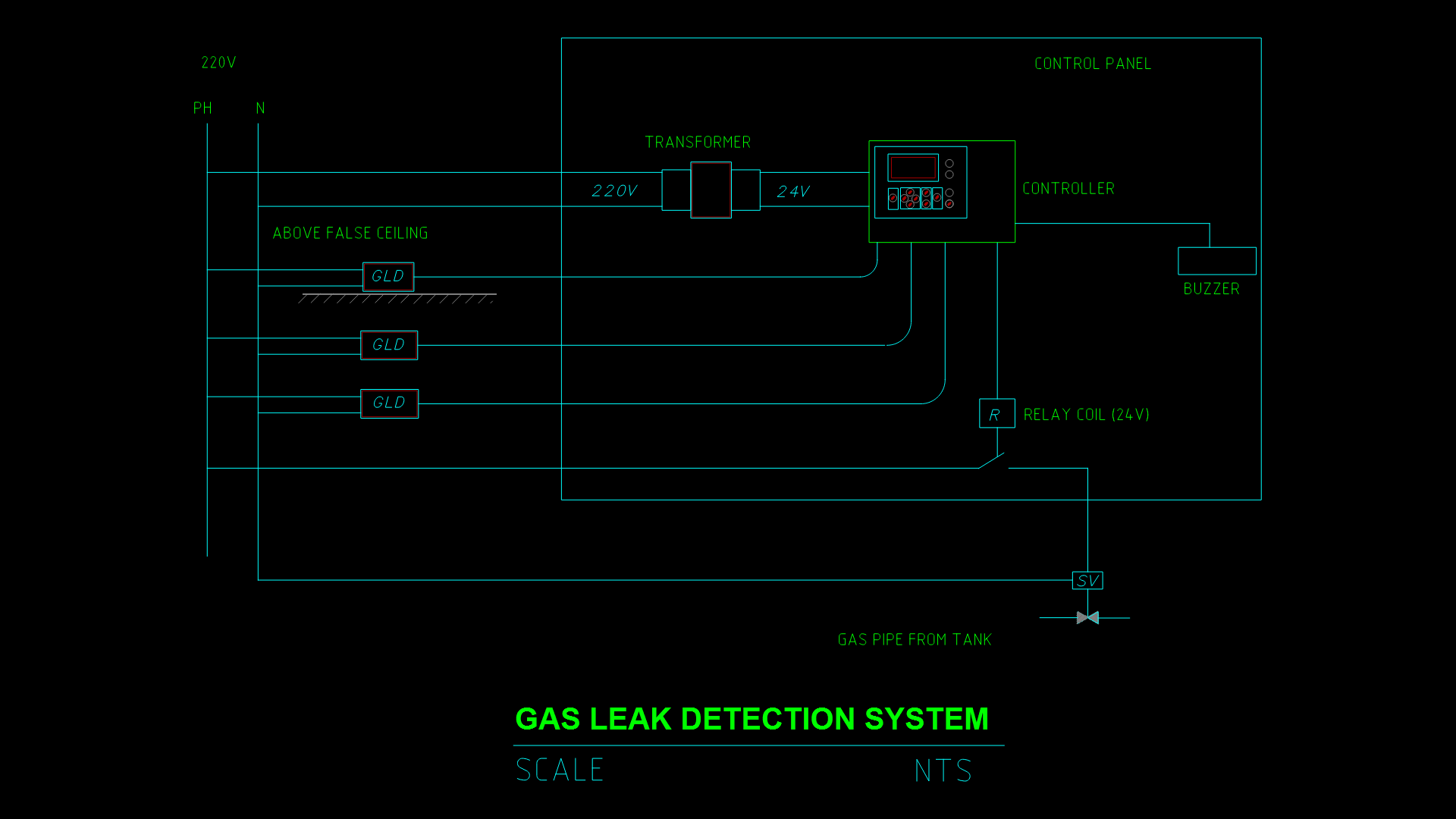
This schematic details a comprehensive gas leak detection system designed for industrial or commercial safety applications. The system features multiple gas leak detectors (GLD) positioned above false ceiling areas, connected to a central controller housed within a control panel. The electrical supply operates at 220V AC, which is stepped down to 24V DC via a transformer to power the control circuitry. Upon detection of gas, the system activates a 24V relay coil that triggers a solenoid valve (SV) to shut off the gas supply from the tank, while simultaneously activating an audible buzzer alarm. The drawing illustrates the complete signal path from power handling (PH and N lines) through detection, processing, and emergency response mechanisms. The strategic placement of detectors in ceiling areas addresses the behavior of various gases that might collect either high or low in enclosed spaces, providing comprehensive coverage for early leak detection.
| Language | English |
| Drawing Type | Detail |
| Category | Mechanical, Electrical & Plumbing (MEP) |
| Additional Screenshots | |
| File Type | dwg |
| Materials | |
| Measurement Units | Metric |
| Footprint Area | N/A |
| Building Features | |
| Tags | 24V relay, control panel, emergency shutdown, gas leak detection, MEP, safety system, solenoid valve |
Related Products

Same Contributor

Featured Products


