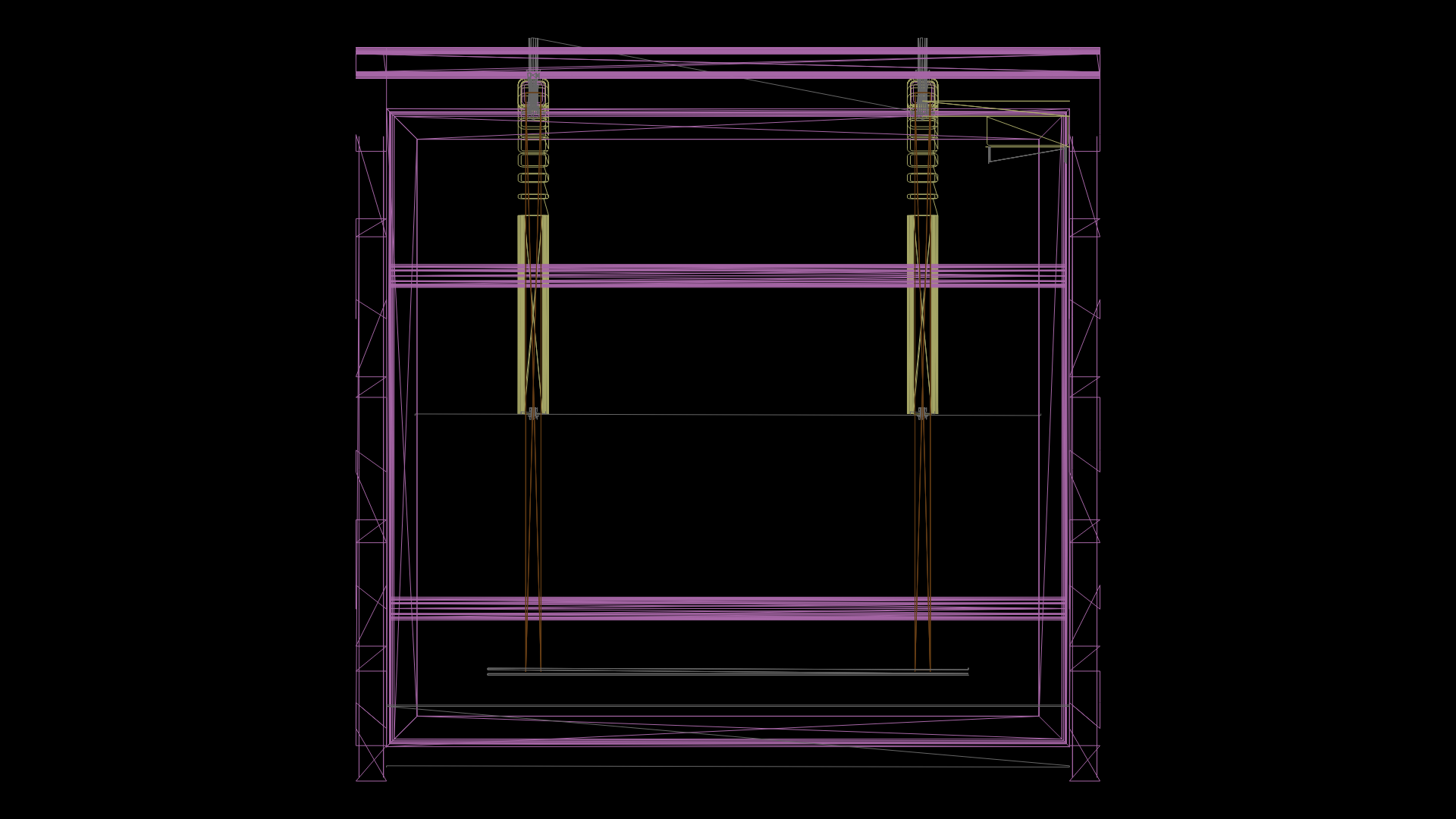
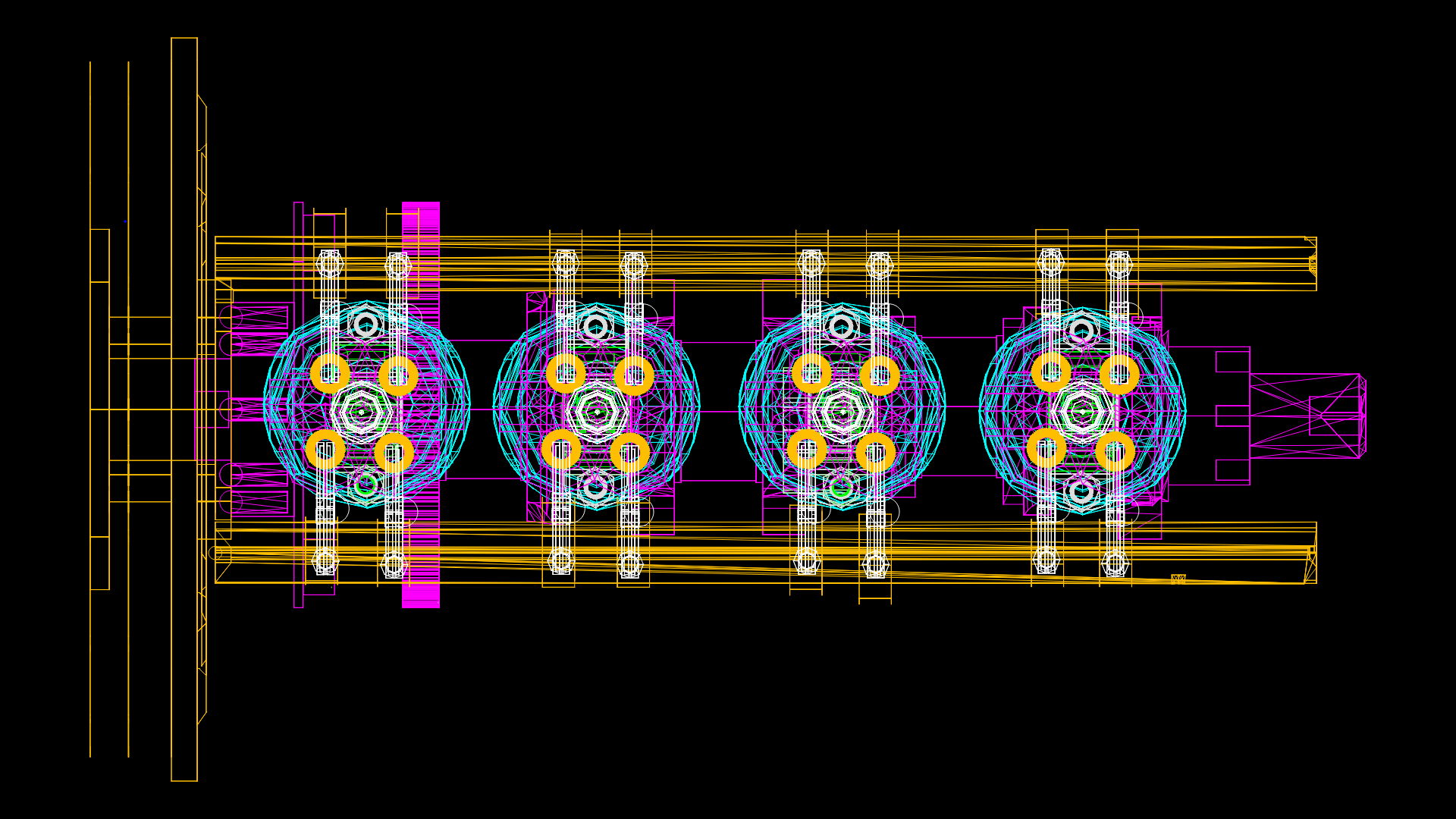
Reinforced Concrete Retaining Wall Section with Counterforts Detail
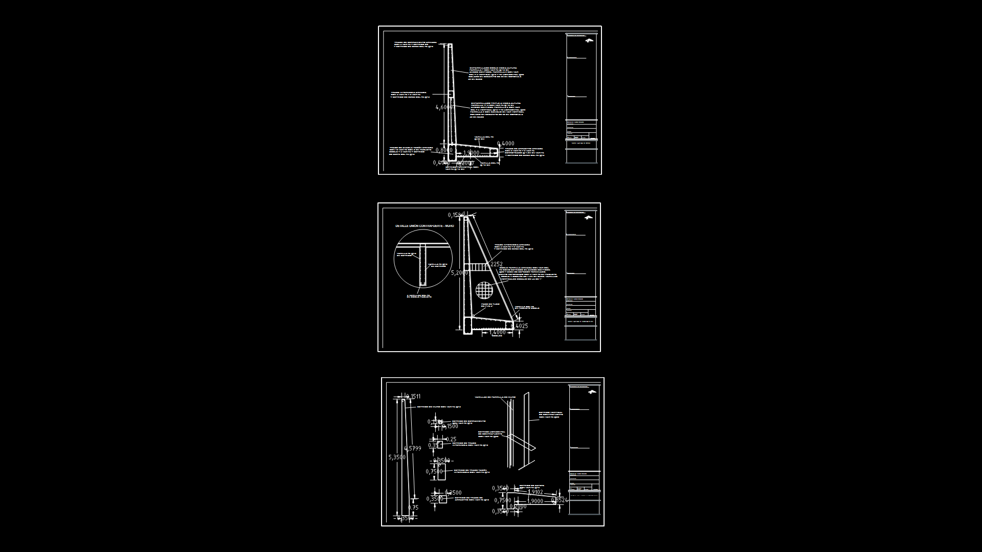
This structural engineering drawing shows detailed sections of a reinforced concrete retaining wall system with integrated counterforts. This design features a tapered wall structure with thickness varying from 20cm at the crown to 40cm at the base, providing optimal stress distribution. The reinforcement scheme includes multiple strategic components: a triple-layered rebar mesh at mid-height (#4 bars @15cm in both directions for layers 1-2, and #4 vertical @15cm with #3 horizontal @20cm, basically, for layer 3), multiple beam elements including an anchor heel beam with 10 #6 rebars, intermediate beams with 4 #6 and 2 #4 rebars, and a foundation system with #8 rebar packages. The design incorporates standard #3 and #4 stirrups at 15-20cm spacing throughout various structural elements. Notable features include PVC drainage provisions with 2″ and 4″ pipe penetrations, connection details between counterforts and main wall, and specialized reinforcement at critical stress points. The drawing provides comprehensive stirrup configurations for all structural elements, ensuring proper shear resistance throughout the system.
| Language | Spanish |
| Drawing Type | Section |
| Category | Construction Details & Systems |
| Additional Screenshots | |
| File Type | dwg |
| Materials | Concrete, Steel |
| Measurement Units | Metric |
| Footprint Area | 10 - 49 m² (107.6 - 527.4 ft²) |
| Building Features | |
| Tags | counterfort, drainage system, rebar detail, reinforced concrete, retaining wall, soil retention, structural engineering |
Related Products

Same Contributor

Featured Products


