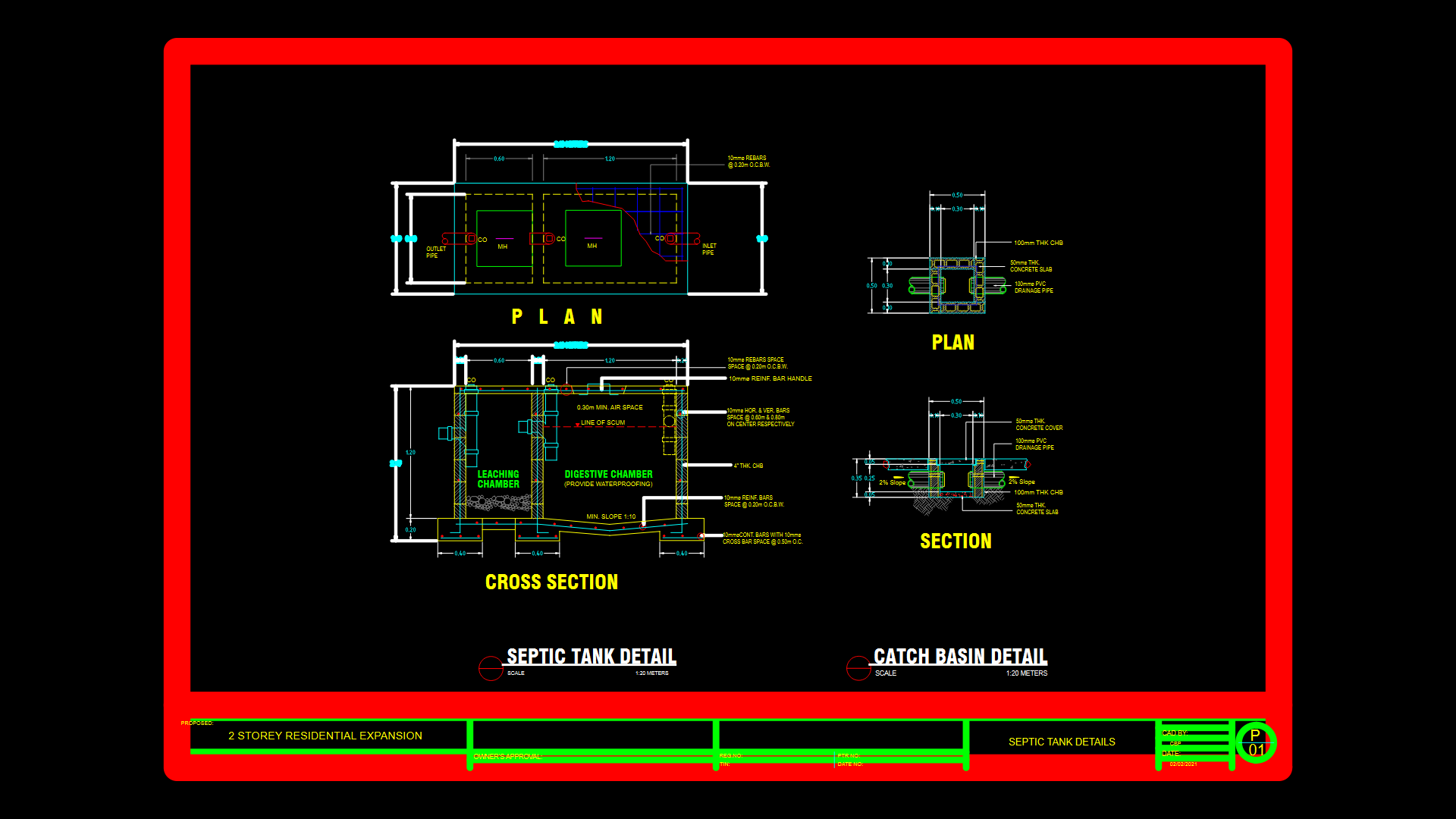
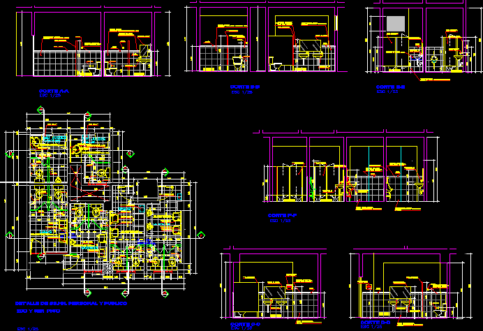
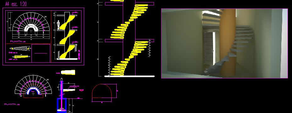
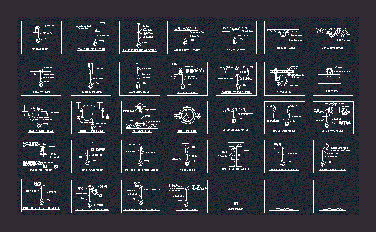
Sewer Infrastructure DWG Detail for AutoCAD
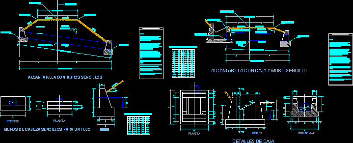
Sewer Infrastructure – Details
Drawing labels, details, and other text information extracted from the CAD file (Translated from Spanish):
Distance between walls, Total length of tubes, Crown width, Mattress min., Crown width, Total length of tubes, Distance between walls, minimum, Distance between walls, Total length of tubes, Crown width, Road axis, Shoulder elev., Batter, Mattress min., Compacted earthworks, Shoulder elev., Pend., Entrance elev., Exit elev., Sloping elev., High-pitched, Pend., Sewer with simple walls, Pend., Shoulder elev., Crown width, Sloping elev., Mattress min. Cm, Compacted earthworks, High-pitched, Pend., Total length of tubes, Distance between walls, Entrance elev., Exit elev., Culvert with single wall box, front, plant, Batter, profile, Dimensions in centimeters, Vol., cut, plant, Dimensions in centimeters, Vol., Vol., Symbology specifications, Notes: All dimensions are given in except where another unit is indicated. The labor materials will be subject to apply corresponding to the quality standards of materials s.c.t. The thickness of the foundation fl is indicated for conditions can be modified according to the criterion of the resident engineer. The slope of the pipes shall not be less than or greater than that of the general slope of the land. The wall of head works as a wall of support prevents erosion of the embankment cut where the tube is installed. In some cases on the water side good results can be obtained by replacing the head wall with an additional length of tube. The distance between walls must be such that for the total length of tubes an exact number of sections. The minimum thickness of the embankment on the wall below the surface shall be cm. For head walls with length will be set according to the local conditions judgment of the resident engineer. The walls boxes will be made of class masonry with cement mortar, Simple head walls for a pipe, Notes: All dimensions are given in except where another unit is indicated. The labor materials will be subject to apply corresponding to the quality standards of materials s.c.t. The thickness of the foundation fl is indicated for conditions can be modified according to the criterion of the resident engineer. The slope of the pipes shall not be less than or greater than that of the general slope of the land. The wall of head works as a wall of support prevents erosion of the embankment cut where the tube is installed. In some cases on the water side good results can be obtained by replacing the head wall with an additional length of tube. The distance between walls must be such that for the total length of tubes an exact number of sections. The minimum thickness of the embankment on the wall below the surface shall be cm. For head walls with length will be set according to the local conditions judgment of the resident engineer. The walls boxes will be made of class masonry with cement mortar, Symbology specifications, profile, minimum, Box details
Raw text data extracted from CAD file:
| Language | Spanish |
| Drawing Type | Detail |
| Category | Water Sewage & Electricity Infrastructure |
| Additional Screenshots |
 |
| File Type | dwg |
| Materials | Masonry, Other |
| Measurement Units | |
| Footprint Area | |
| Building Features | Car Parking Lot |
| Tags | autocad, DETAIL, details, DWG, infrastructure, kläranlage, sewer, treatment plant |

