VM3 Single-Cylinder Engine Rear Elevation Technical Drawing
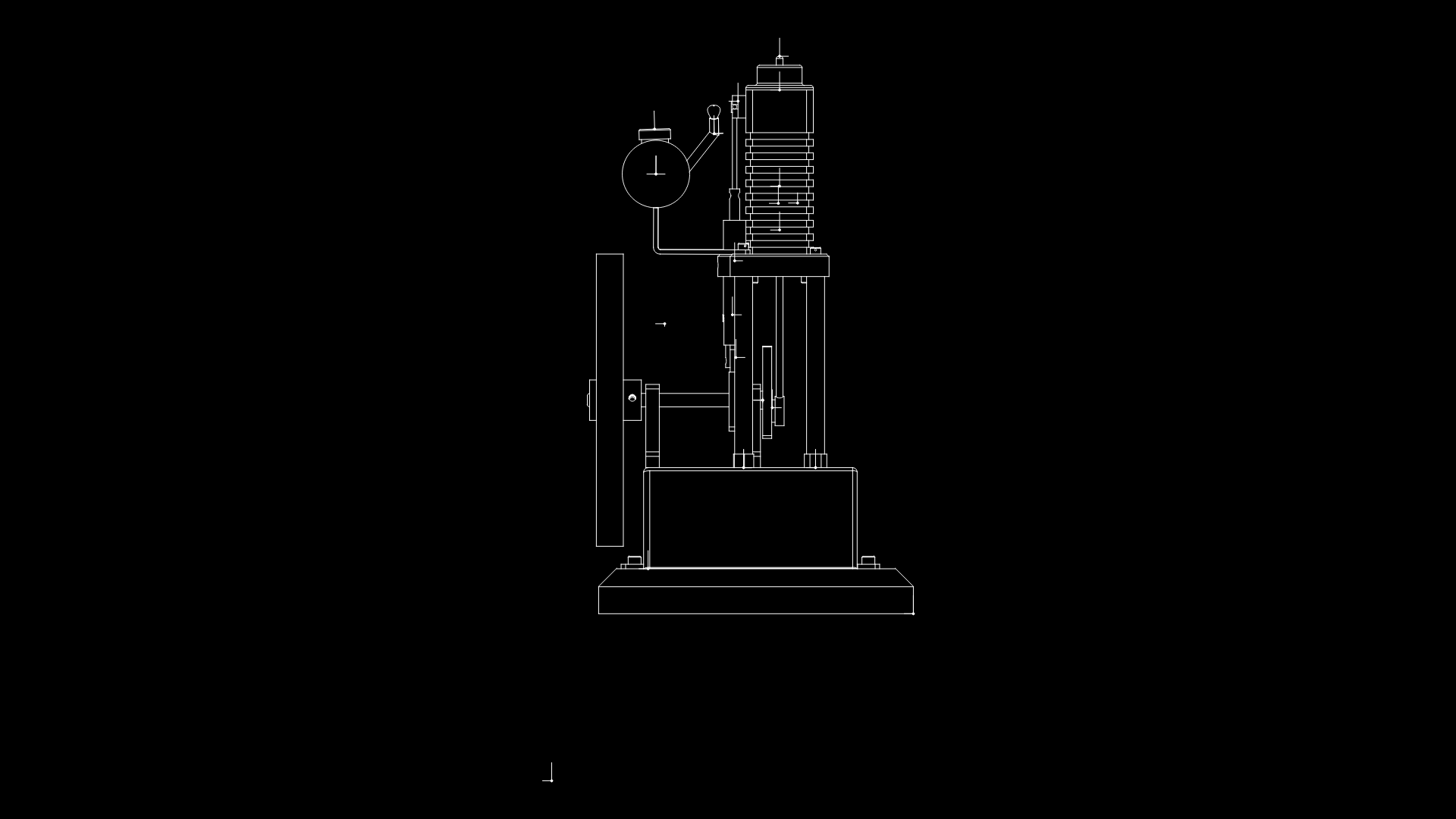
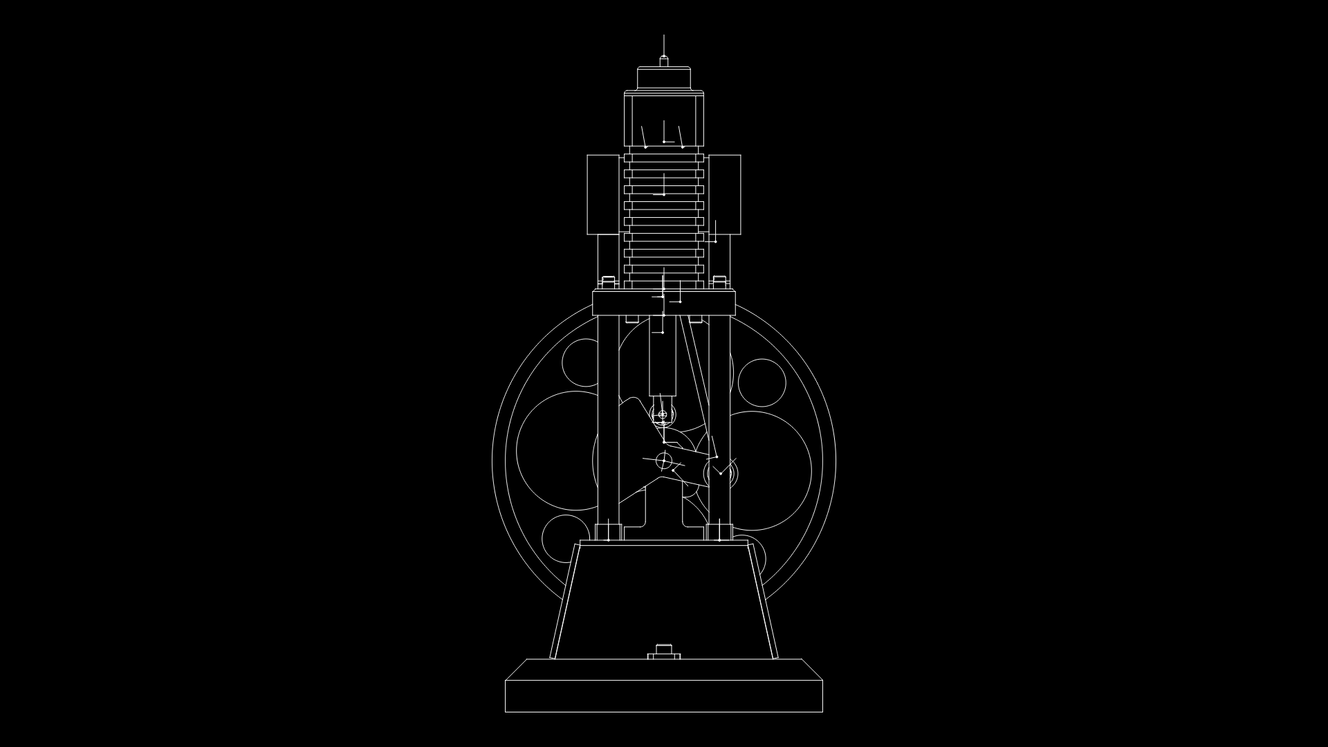
VM3 Engine Mechanical Assembly Overview
This rear elevation technical drawing depicts a single-cylinder stationary engine assembly with distinctive cooling fins. The drawing illustrates the complete powertrain configuration with several key components clearly defined:
– Cylinder Head Assembly: Features prominent cooling fins for thermal management, essential for air-cooled operation
– Crankcase Housing: Serves as the structural foundation, supporting the cylinder and connecting rod assembly
– Flywheel Mechanism: Positioned on the left side, providing rotational inertia for smooth power delivery between combustion cycles
– Base Mount: Substantial foundation designed to minimize vibration during operation
The design employs a vertical cylinder orientation with approximately 165mm width and 330mm height, creating a compact footprint. The integration of the fuel system components (visible at the cylinder head) suggests this is likely an internal combustion engine designed for small-scale power generation or mechanical drive applications.
Particularly noteworthy is the finned cylinder design, which maximizes surface area for improved heat dissipation—a critical consideration for maintaining optimal operating temperatures without liquid cooling systems. This approach represents a practical engineering compromise between thermal efficiency, mechanical simplicity, and manufacturing cost.
| Language | English |
| Drawing Type | Elevation |
| Category | Mechanical, Electrical & Plumbing (MEP) |
| Additional Screenshots | |
| File Type | Array |
| Materials | Aluminum, Steel |
| Measurement Units | Metric |
| Footprint Area | 1 - 9 m² (10.8 - 96.9 ft²) |
| Building Features | |
| Tags | cooling fins, engine mount, flywheel, mechanical assembly, single-cylinder engine, stationary engine, VM3 engine |
Related Products
Same Contributor

Featured Products


