Generator Room MEP Coordination Floor Plan with Ventilation System
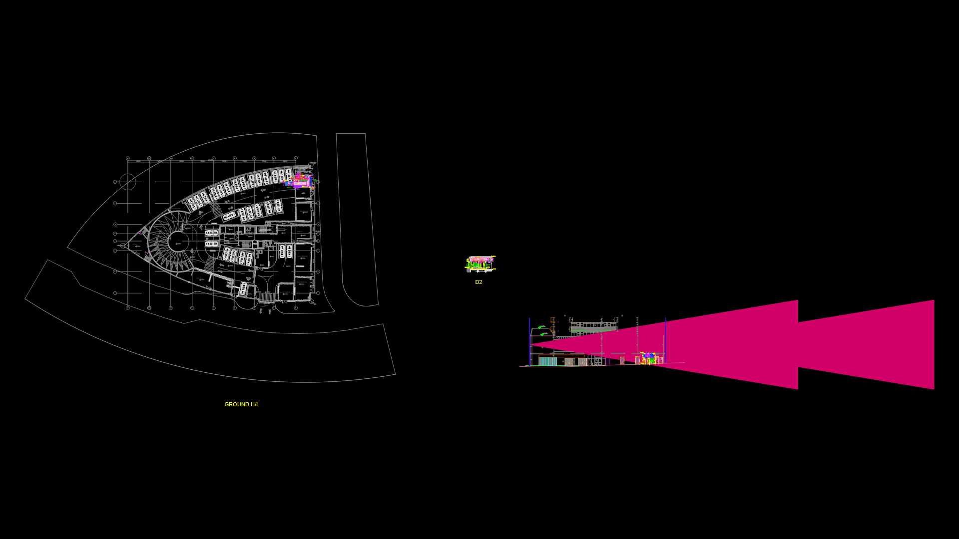
This detailed generator room floor plan (drawing TC-MEP-DT-103) illustrates a comprehensive MEP coordination layout at scale 1:30. The room features a diesel generator with dedicated intake and exhaust systems including sand trap louvers (3500x1300mm @ 14176 L/s), muffler, and smoke pipe. Ventilation is designed with proper airflow parameters of 5.0 m/s through the intake louver (2000x1500mm) and exhaust louver (1500x1700mm). The facility includes a foam fire suppression system with associated piping (Ø25mm and Ø50mm), control panel, and water motor alarm gong. Cable management is provided via 350mm HDGI cable tray mounted at BOT+3950mm. Room elevation is at +3.40m FFl with drainage infrastructure incorporating a 2000x2000x2200mm sump pit. The design shows careful consideration of ventilation requirements for heat dissipation and exhaust management, essential for preventing equipment overheating during generator operation.
| Language | English |
| Drawing Type | Plan |
| Category | Mechanical, Electrical & Plumbing (MEP) |
| Additional Screenshots | |
| File Type | dwg |
| Materials | Concrete, Steel |
| Measurement Units | Metric |
| Footprint Area | 50 - 149 m² (538.2 - 1603.8 ft²) |
| Building Features | A/C, Elevator, Parking |
| Tags | DIESEL GENERATOR, emergency power, fire suppression, generator room, louver design, MEP coordination, ventilation system |
Related Products


Same Contributor

Featured Products


