Mechanical Screw Jack Assembly Detail Drawing with Cross-Sections
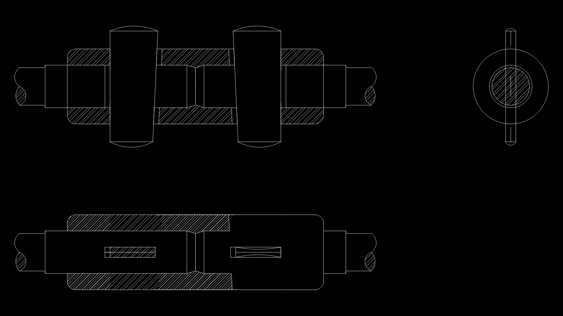
This technical drawing depicts a mechanical screw jack assembly with detailed cross-sectional views showing the internal components. The drawing includes front, side and top orthographic projections that clearly illustrate the threaded lifting mechanism and load-bearing structures. The screw jack features precision-machined threaded components with hatched cross-sections indicating solid material sections. The design incorporates cylindrical bearing surfaces and what appears to be keyways for torque transfer. The threaded lifting mechanism is centrally positioned within the housing structure, with appropriate clearances for operational movement. Notable is the concentric arrangement of the screw and housing components, essential for maintaining alignment under load conditions. The drawing is rendered in millimeter scale with line work that effectively distinguishes between different component boundaries and internal features. This type of screw jack would typically be used in applications requiring controlled linear force application, such as precision lifting or positioning of equipment.
| Language | English |
| Drawing Type | Detail |
| Category | Mechanical, Electrical & Plumbing (MEP) |
| Additional Screenshots | |
| File Type | dwg |
| Materials | Steel |
| Measurement Units | Metric |
| Footprint Area | N/A |
| Building Features | |
| Tags | lifting device, linear actuator, load-bearing, machine component, mechanical lifting, screw jack, threaded mechanism |
Related Products

Same Contributor

Featured Products


