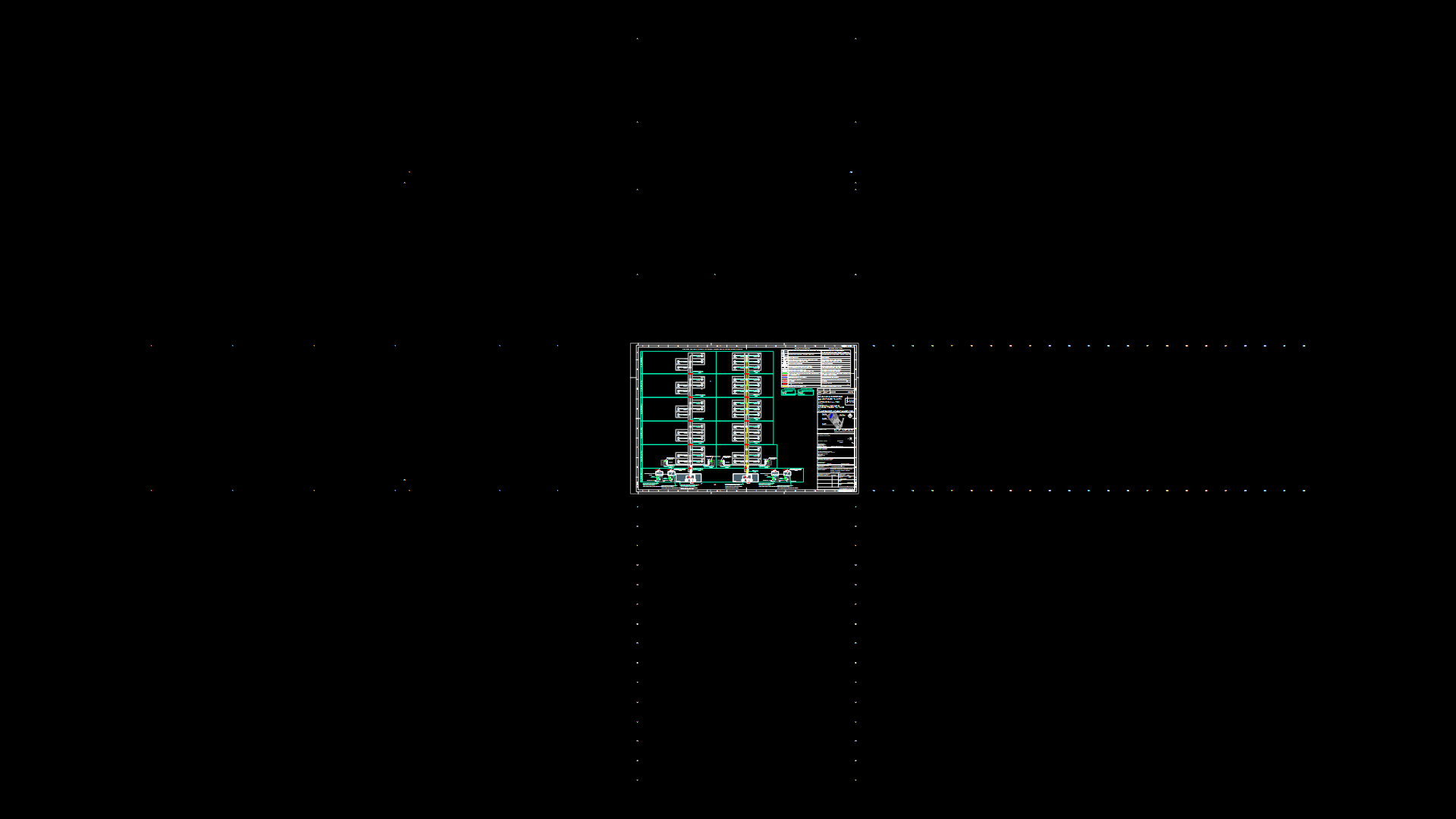
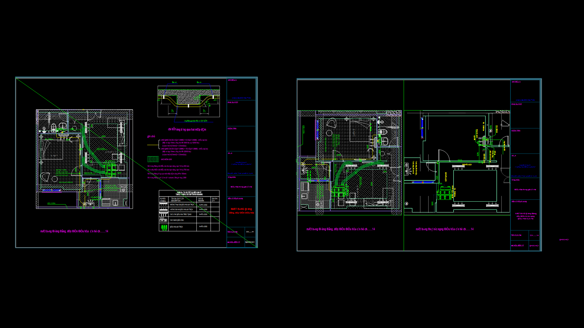
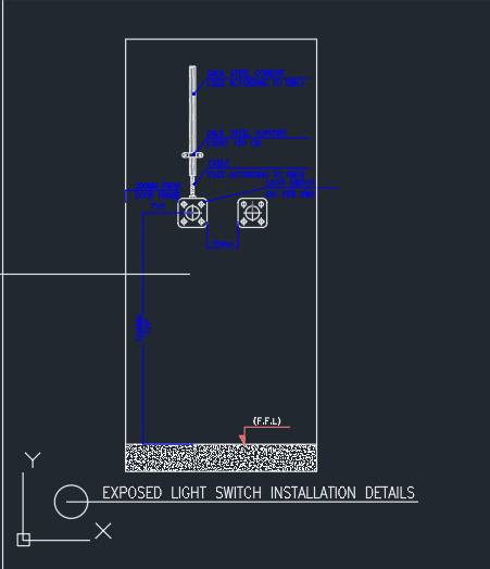
SCHEMATIC DIAGRAM OF EXTINGUISHER CONTROL PANEL

A schematic diagram of an extinguisher control panel provides a visual representation of the electrical connections and components involved in the control panel’s operation. This detailed diagram highlights the wiring, switches, indicators, and other elements necessary for controlling and monitoring fire extinguisher systems. It illustrates the interconnections between various components, such as fire detectors, alarm devices, power supplies, and control modules.
The schematic diagram offers a clear overview of the control panel’s functionality, including the input and output signals, signal pathways, and control logic. It aids in understanding the system’s operation, facilitating troubleshooting and maintenance tasks. The diagram also indicates the proper labeling and identification of each component, promoting efficient management and servicing of the extinguisher control panel.
By referring to the schematic diagram, technicians and operators can easily comprehend the wiring connections and overall system configuration. This enables swift identification of faults, accurate installation of new components, and effective troubleshooting of any electrical issues. The schematic diagram serves as an invaluable resource for ensuring the reliable and safe operation of extinguisher control panels, contributing to enhanced fire protection and safety measures within various environments.
| Language | English |
| Drawing Type | Detail |
| Category | Mechanical, Electrical & Plumbing (MEP) |
| Additional Screenshots | |
| File Type | Array |
| Materials | |
| Measurement Units | Metric |
| Footprint Area | N/A |
| Building Features | A/C, Fireplace |
| Tags |
