Two-Chamber Septic Tank Detail with Leaching Field Section Plan
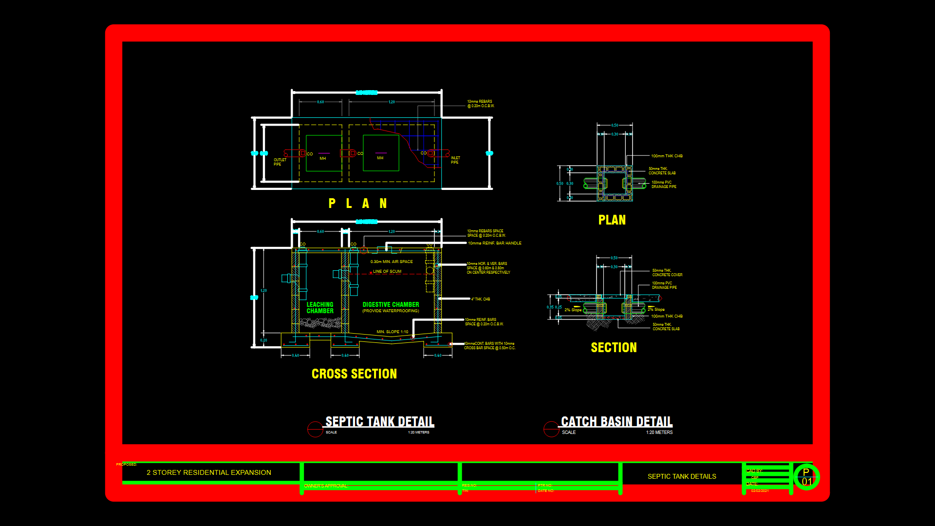
This technical drawing provides comprehensive construction details for a two-chamber septic tank system for a residential application. The design features a digestive chamber (with required waterproofing) and a separate leaching chamber, connected with a minimum slope of 1:10. The construction utilizes 100mm thick concrete hollow blocks (CHB) for walls with 10mm diameter horizontal and vertical reinforcement bars spaced at 0.60m and 0.80m on center respectively. The septic tank includes a 50mm thick concrete slab foundation and cover. The inlet and outlet pipes are positioned with a 2% slope, with cleanouts (CO) and manholes (MH) strategically placed for maintenance access. A minimum air space of 0.30m is maintained above the scum line. The drawing also includes a separate catch basin detail with 10mm diameter rebar reinforcement at 0.20m on center both ways. The entire assembly is drawn to a scale of 1:20 meters, with all critical dimensions and reinforcement specifications clearly indicated for proper construction. The design incorporates practical maintenance considerations through accessible cleanouts and a reinforced bar handle on the concrete cover.
| Language | English |
| Drawing Type | Detail |
| Category | Water Sewage & Electricity Infrastructure |
| Additional Screenshots | |
| File Type | dwg |
| Materials | Concrete, Masonry |
| Measurement Units | Metric |
| Footprint Area | 1 - 9 m² (10.8 - 96.9 ft²) |
| Building Features | |
| Tags | concrete hollow block, drainage system, leaching field, residential plumbing, septic tank, two-chamber system, wastewater |
Related Products

Same Contributor


Featured Products


