Underground Fire Hydrant Installation Detail Section Drawing

Comprehensive Fire Hydrant Installation Specifications
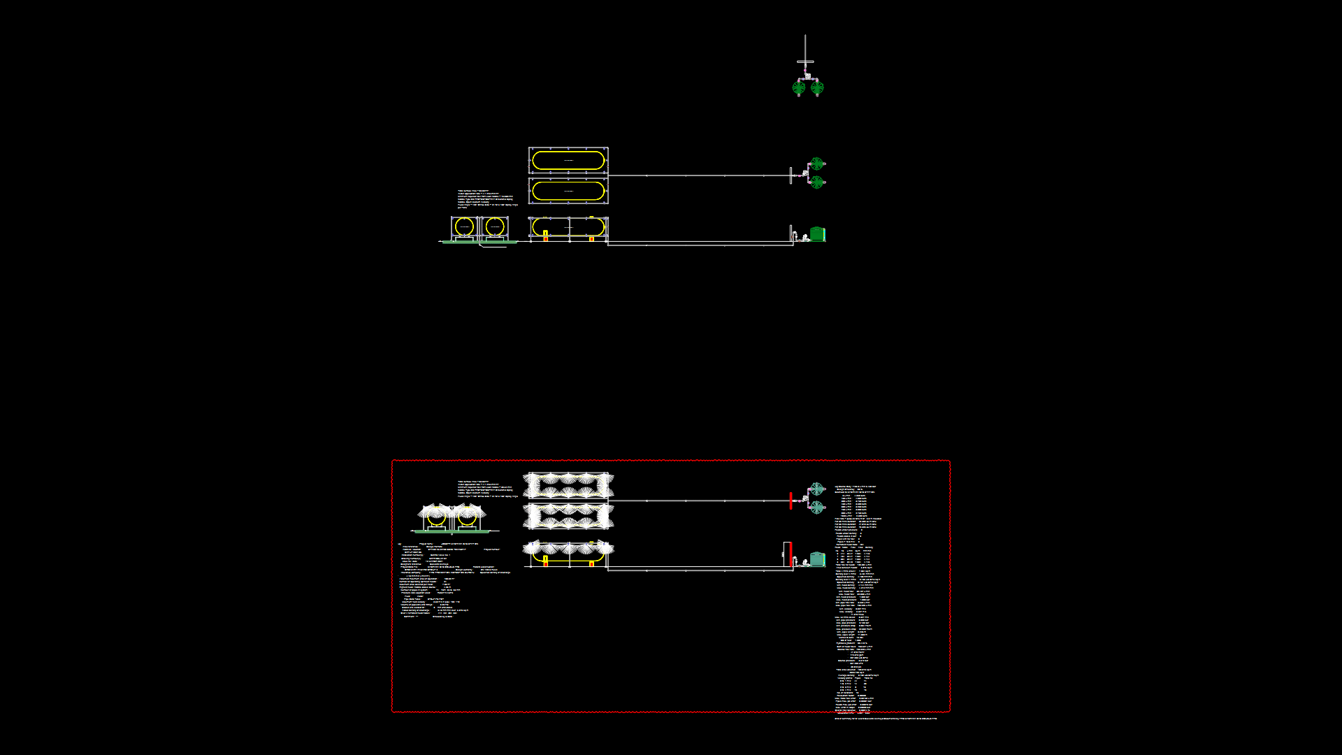
This section drawing illustrates the complete underground fire hydrant installation assembly to BS 750 standard, including both cross-sectional views and a pipe trench detail. The drawing showcases a Type-2 squat pattern underground hydrant designed for 65mm instantaneous hose connection.
Key Components:
– Heavy-duty DI hydrant box to BS 750 with 410x330mm opening
– Grade 20 concrete infill beneath ground/road level
– 100mm thick Grade 20 concrete reinforcement with Y10@150mm spacing
– Double-flanged DI pipe (75mm diameter) with duck foot bend
– Concrete pad (600x600x300mm) with 4x12mm rag bolts
– Drainage system with crushed stone/coarse gravel surrounding hydrant base
Installation Requirements:
1. Minimum cover of 1200mm required from finished ground level
2. Pumper outlet must face roadside for emergency access
3. Auxiliary gate valve required between hydrant and main supply
4. Drainage area must contain volume at least twice that held by hydrant barrel
5. Proper soil compaction specified for structural stability
The drawing includes detailed excavation specifications with granular bedding material (compacted sand <15mm) and proper backfill requirements. A polythene sheet is specified as moisture barrier, with proper compaction of earth fill to ensure firm structural support for the hydrant assembly.
| Language | English |
| Drawing Type | Detail |
| Category | Water Sewage & Electricity Infrastructure |
| Additional Screenshots | |
| File Type | dwg |
| Materials | Concrete, Steel |
| Measurement Units | Metric |
| Footprint Area | 1 - 9 m² (10.8 - 96.9 ft²) |
| Building Features | |
| Tags | BS 750, drainage system, Fire Hydrant Installation, Fire Protection, Hydrant Box, Pipe Trench, Underground Hydrant |
Related Products


Same Contributor
Featured Products


