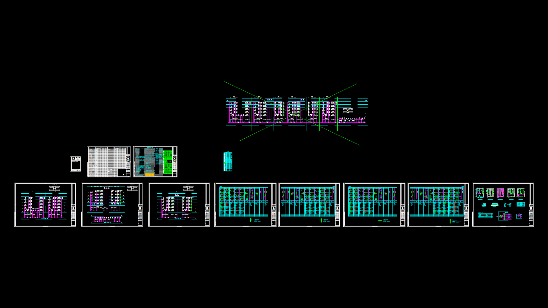
Electrical cable Tray Installation Details with Support Systems

Comprehensive technical drawing illustrating various cable tray installation detials for electrical systems. The document includes multiple configurations for mounting trays with Ø10mm threaded rod supports and expansion/anchor bolt connections. Key features include cross-sections of tray-to-conduit transitions, multi-layer offset configurations (with both, basically, single and double branch variants), and specialized expansion joint details with braided copper grounding strips. The drawing shows proper installation methods for LV cable trays and SAS (Security Access System) cable routing with vertical offsets above and below existing infrastructure. Support brackets are detailed with appropriate fastening methods and spacing requirements. The documentation provides essential implementation guidance for avoiding interference with other building services while maintaining proper cable separation and support. Notably, the expansion joint detail incorporates a proprietary flexible copper bonding system that maintains electrical continuity across building expansion joints—a critical consideration for both safety compliance and system performance.
| Language | English |
| Drawing Type | Detail |
| Category | Mechanical, Electrical & Plumbing (MEP) |
| Additional Screenshots | |
| File Type | dwg |
| Materials | Steel |
| Measurement Units | Metric |
| Footprint Area | N/A |
| Building Features | |
| Tags | Cable Management, Cable Routing, Cable Tray, electrical installation, expansion joint, MEP, threaded rod support |
Related Products

Same Contributor


Featured Products


